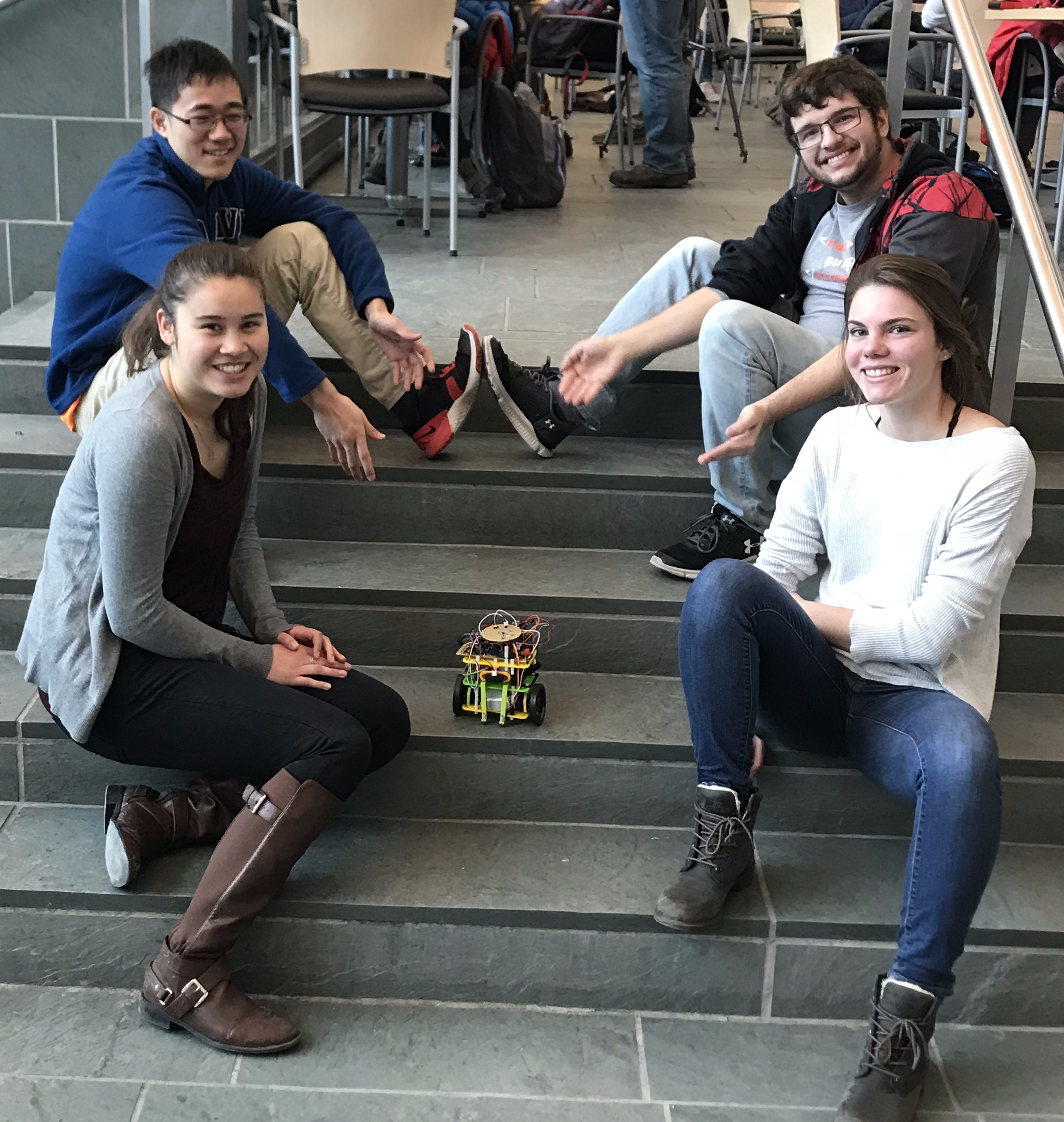
We are the 7-Ups, and welcome to our website! For the entire Fall 2018 semester, we worked together
on our little robot friend to make sure they could be the most bubbly effervescent go-getter in
the maze! Here's our family photo:
Please read through the website to see how our little buddy grew up and for tips on how to make your
own robot!
Members
Xiaoyu Yan
Junior ECE
Christine Mayer
Junior ECE
Patrick Clobridge
Senior ECE
Tara Van Nieuwstadt
Junior ECE
Contract
Ethics
Labs
Lab 1
Lab 2
Lab 3
Lab 4
Milestones
Milestone 1
Milestone 2
Milestone 3
Milestone 4
Final Implementation
Tutorials
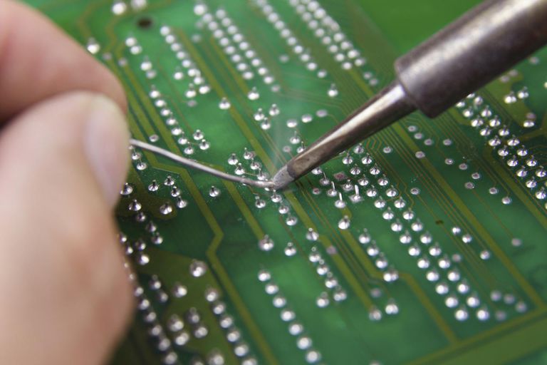
Intro to Soldering
Muxing
Copyright would go here, but we don't need it.
ROBOT
Introduction
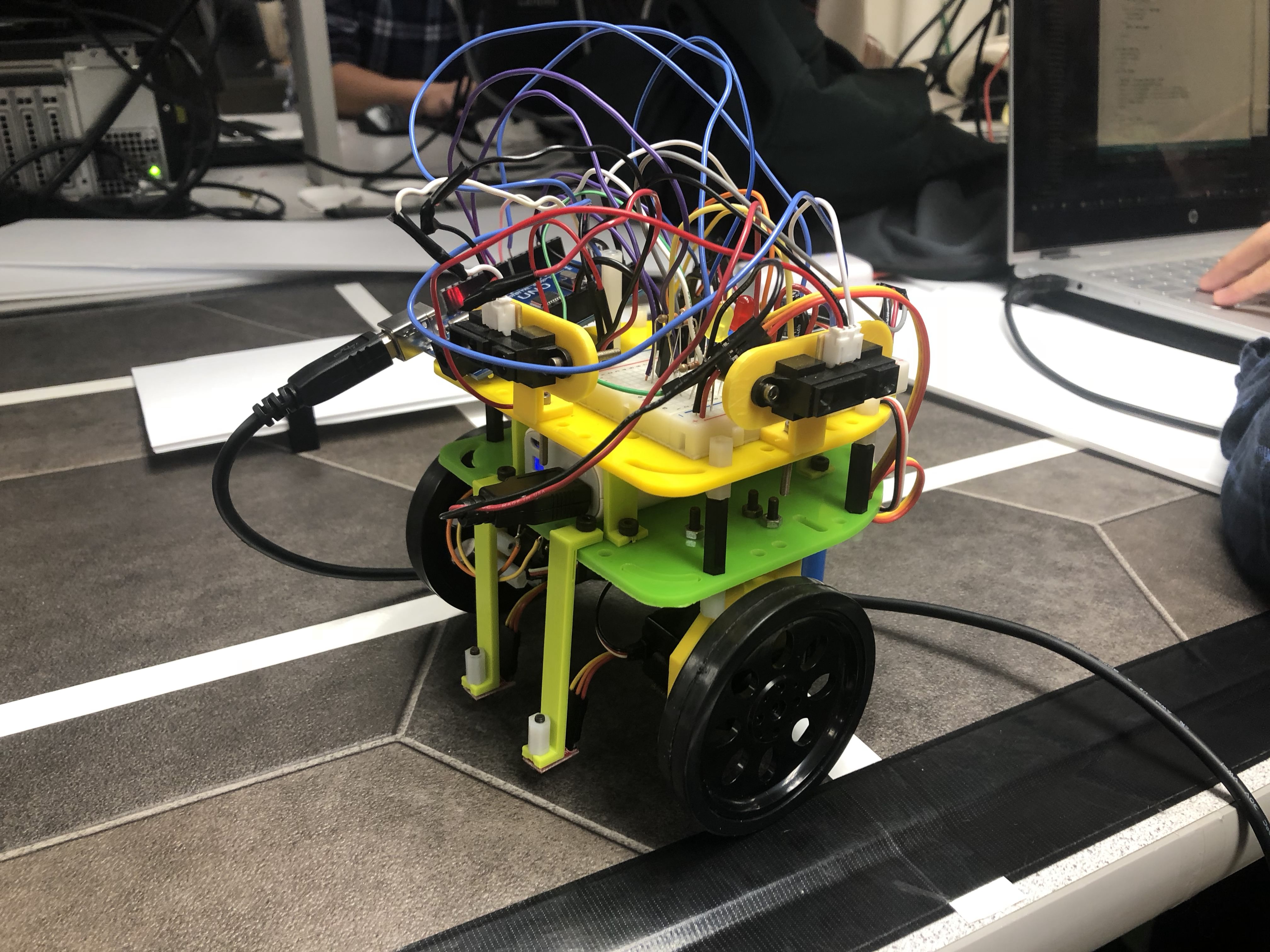
Meet our robot friend! This little guy was built for ECE 3400, Intelligent Physical Systems, to complete the tasks of the final competition.
In our robot's final design, we redesigned the overall layout of the robot, making
both electrical and mechanical improvements. This entire project is
the culmination of a fully autonomous robot using many aspects over many different types
of wired/wireless communications, peripherals, data structures, computer architectures,
and system design. It is the peak of a junior design project. Over the course of four
labs and four milestones, we have taught our robot how to follow a line, operate a
servo, navigate with walls, communicate with another arduino, detect color,
and think about where to move next. The biggest challenge of all was to move past
the prototyping stage and integrate an optimized version of the robot with better
power utilization, mechanical dexterity, and algorithmic precision. Although by
competition we were unable to fully integrate our perfected robot, we incrementally demonstrated
that our components worked to expectation.
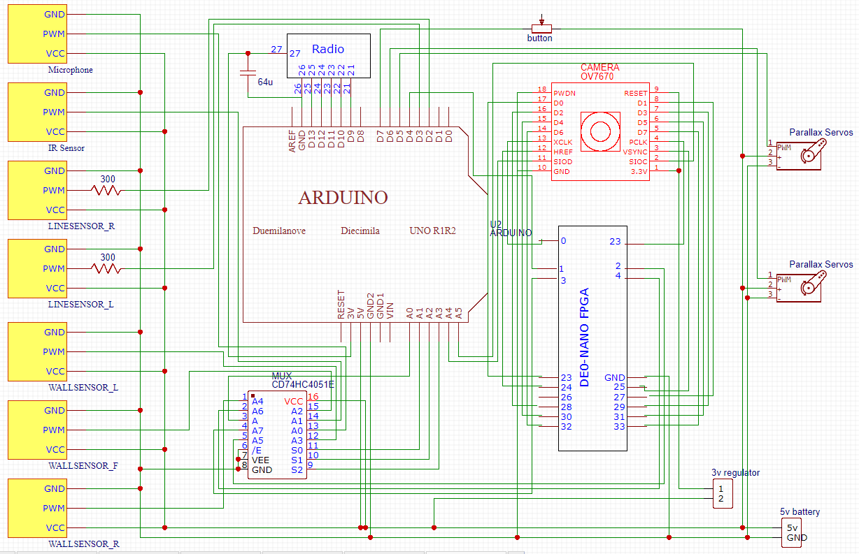
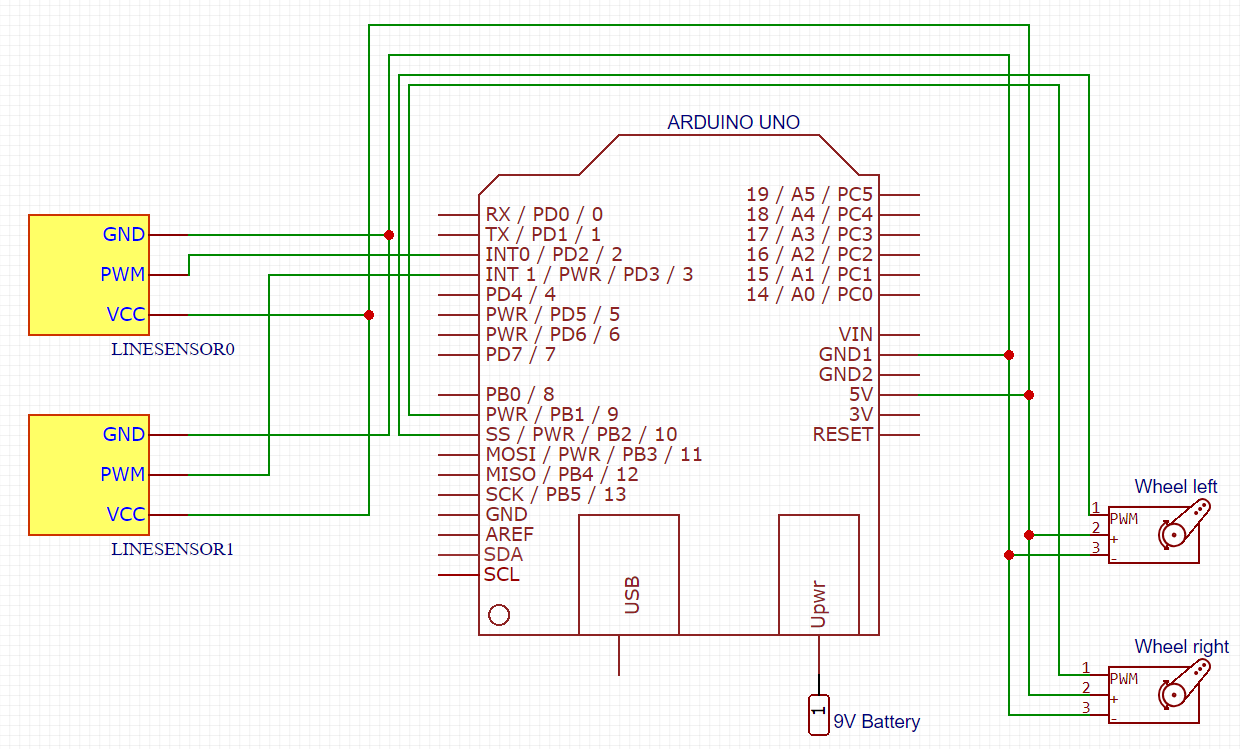
Schematic of Final Robot
Progression
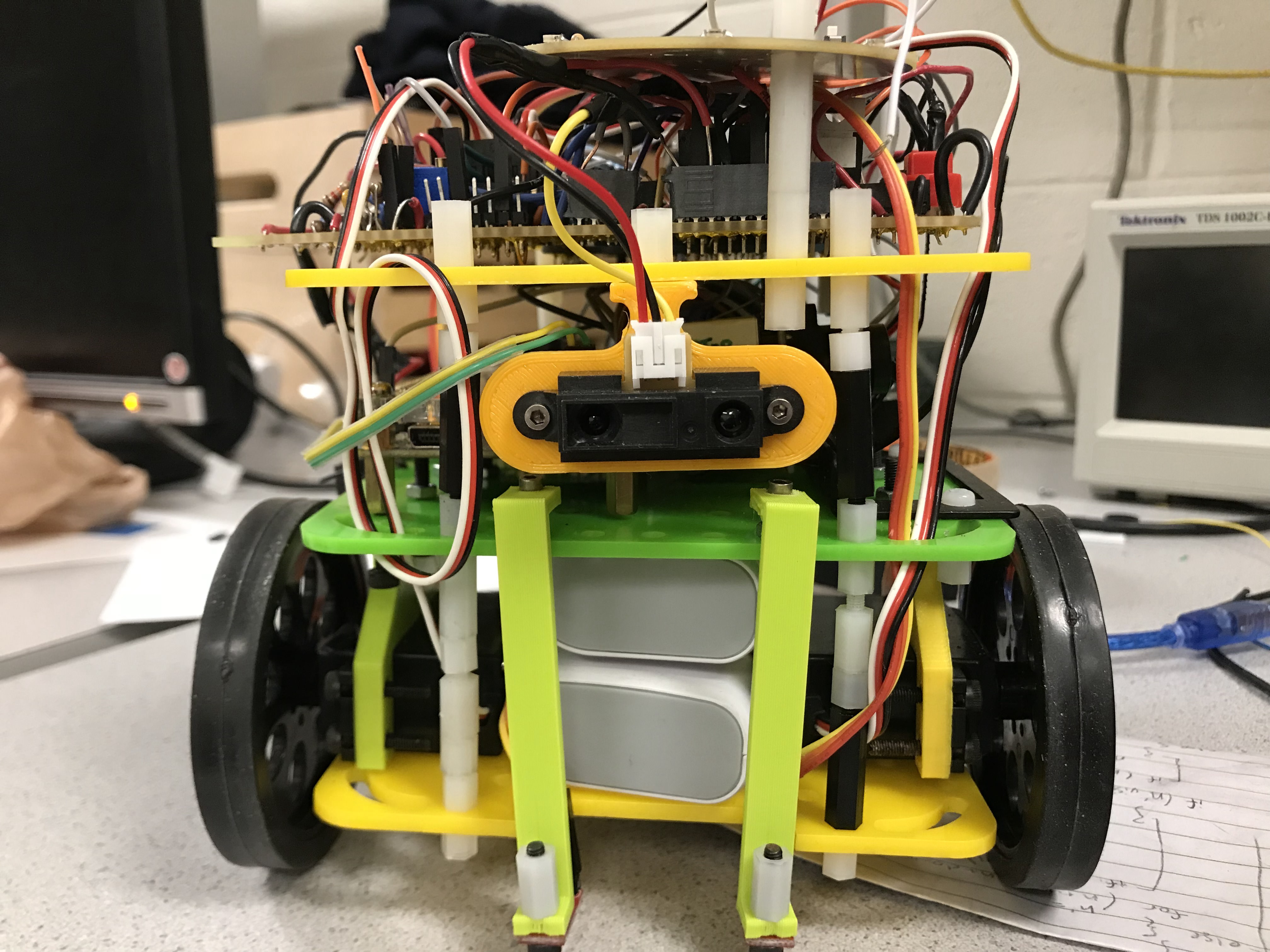
Line Sensor
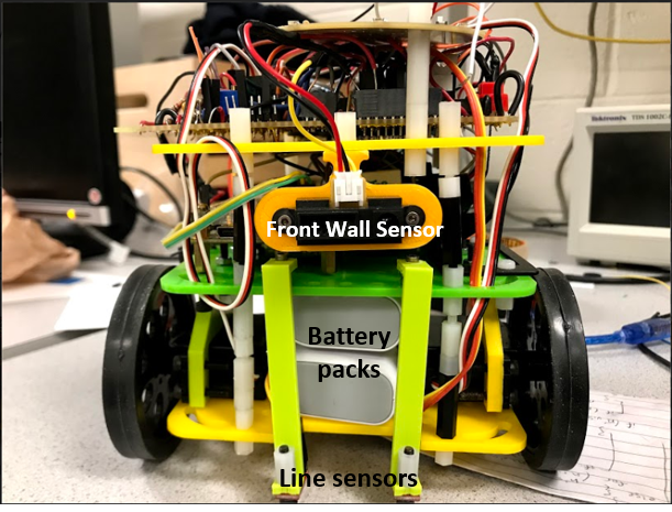
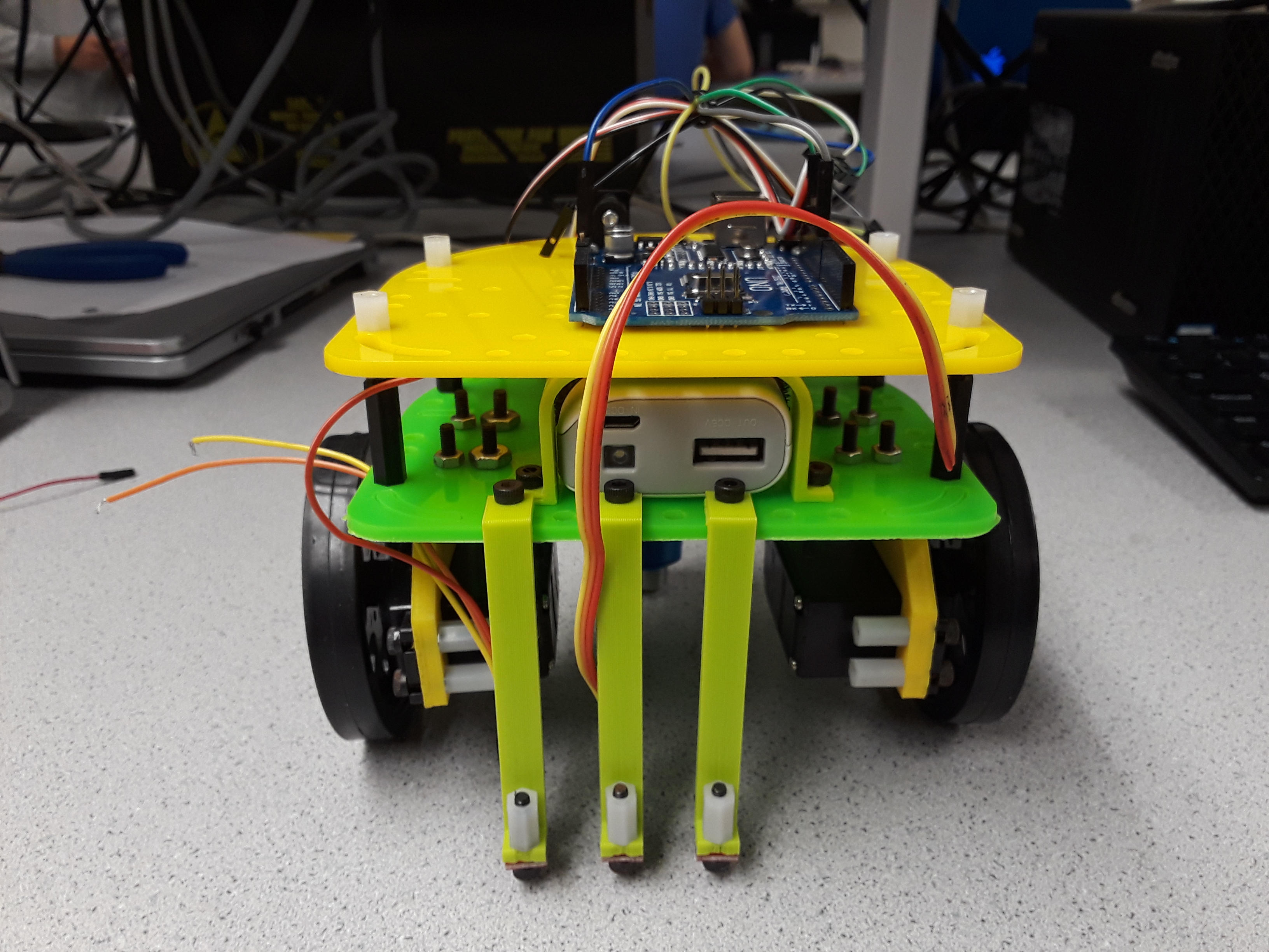
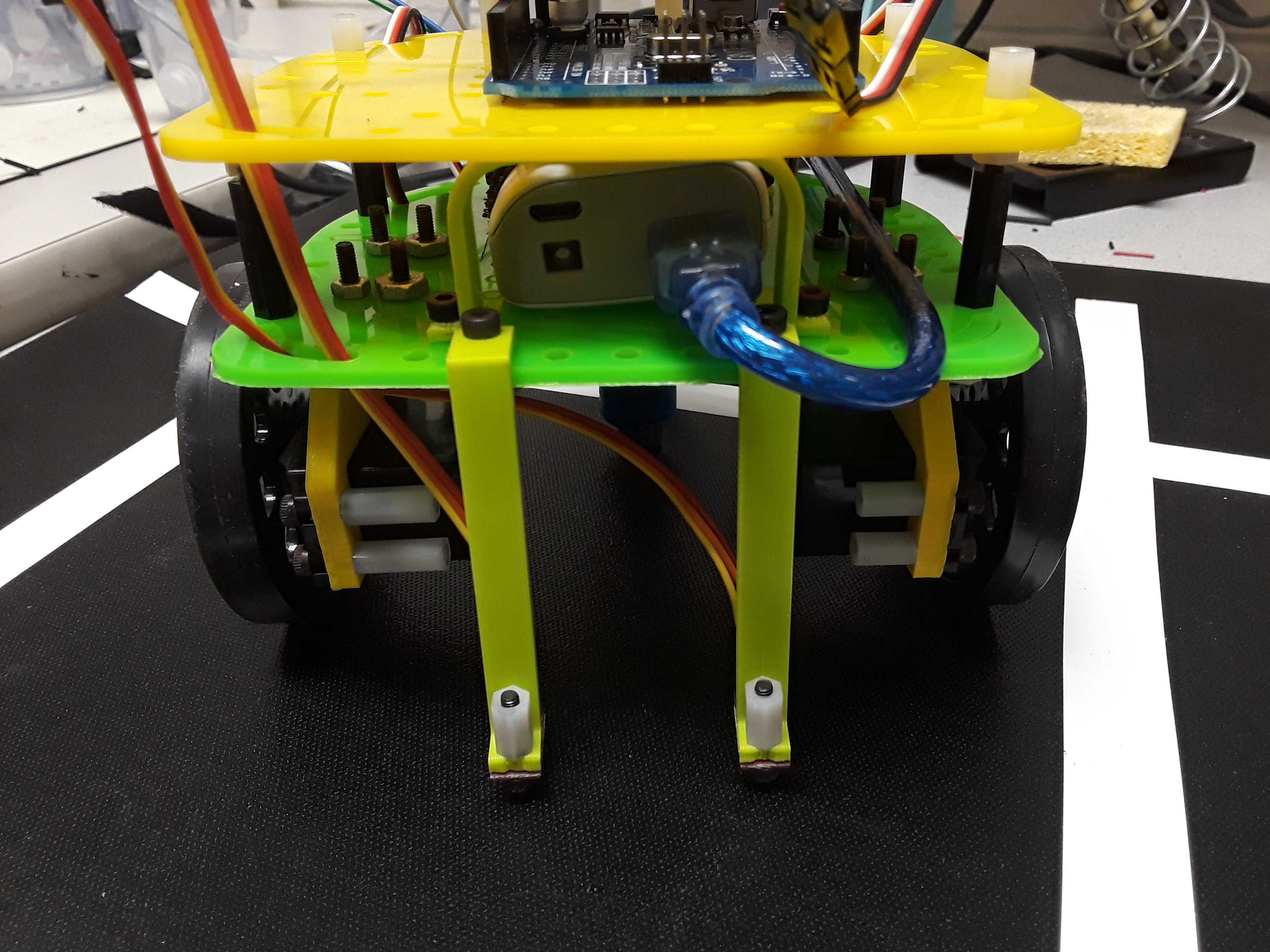
Front View of the Robot
We implemented a simple design with two line sensors, each to the side of the
line. If one line sensor detects the white, we turn in the direction that moves the
line sensor back into the unlined surface. So, if the left sensor detects the line, we turn a little bit to the
left and vice versa. Below is a demonstration of the line following capabilities:
In our demonstration, the robot smoothly follows the line. An interseciton is detected if both sensors see a
line. In a more complex implementation, we were able to
program the robot to move in a figure 8, demonstrating that the robot can properly send PWM signals to the Servos
while also detecing intersections.
Wall Detection and Maze Movement
For the second milestone of the project, we our robot detects walls and decides how to
turn at the intersection. Since
our plan of a maze movement algorithm was simple, just left-wall following, we only used two IR distance sensors to detect the walls, placed the wall sensors on the
left and front of the robot. Of course, a u-turn is not
as simple as it would be in the final design. In order to execute the u-turn, we detect the wall twice: in the initial instance
and once again after we turned. The implementation worked reliably.
Integration of IR and Microphone
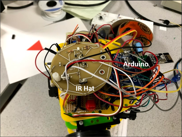
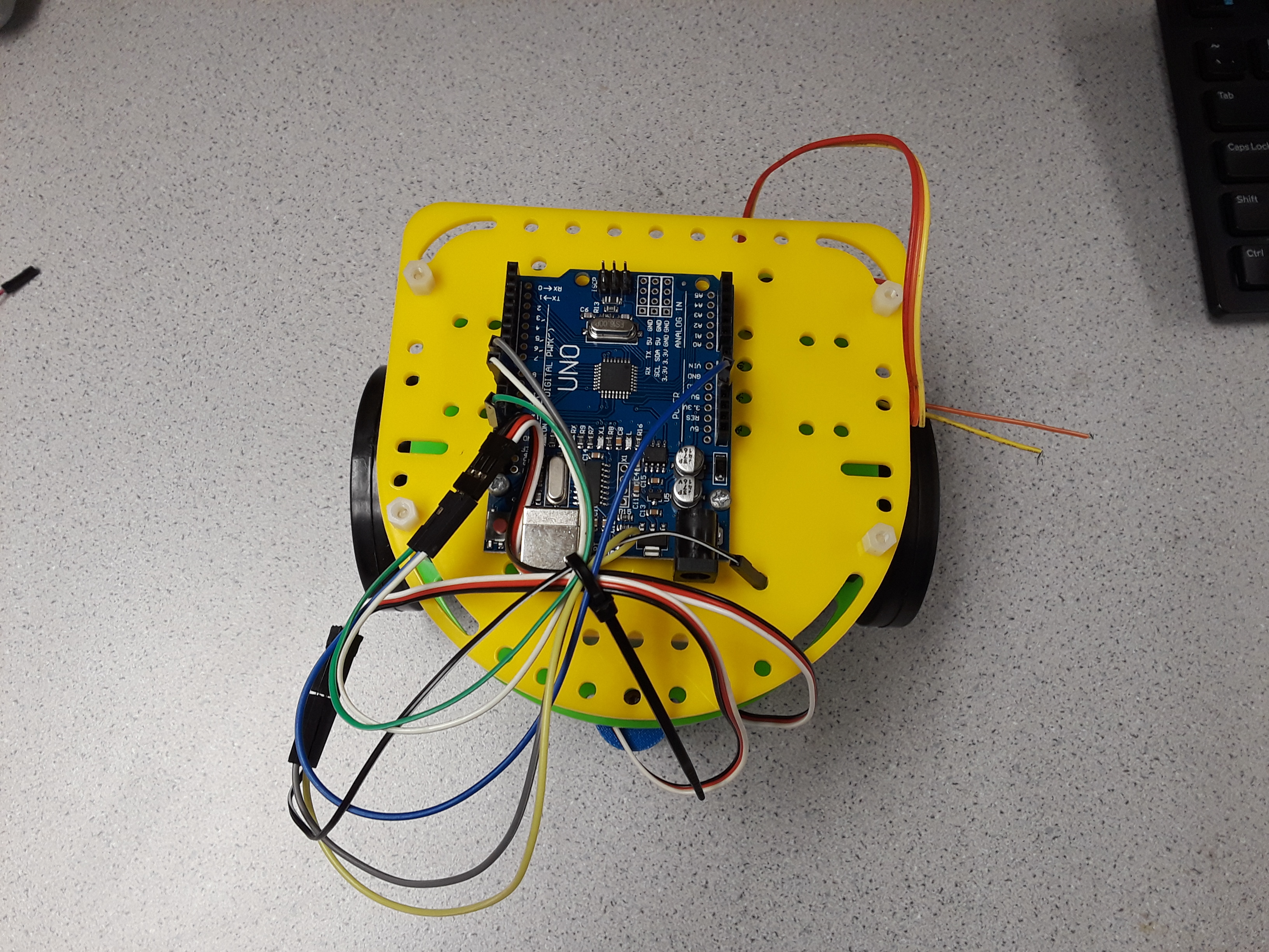
Top View with IR Hat
Now its time for the robot to interact with us and other robots with the aid of IR and audio
signals. For the IR sensor, we use Infra-Red (IR) light to detect the presence of another robot (or a decoy).
The IR sensor uses a Phototransistor to convert the light into a signal for the robot to convert into individual
frequencies. To convert the signal into these individual frequencies, we used Fast Fourier Transform (FFT). Although
it is a rather hefty algorithm that requires a lot of space, it is essential. For the IR Sensor, we built the following
circuit to amplify the incoming signal:
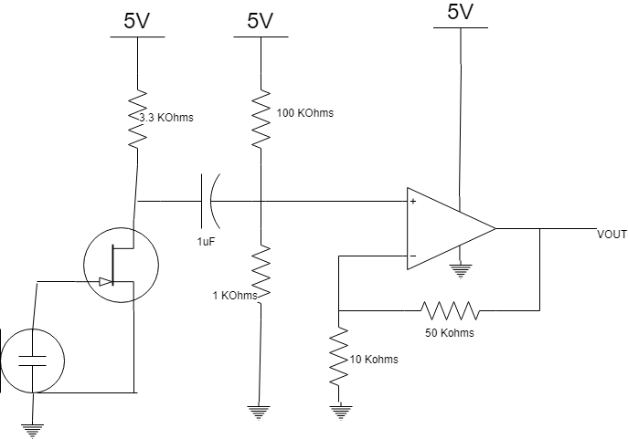
Schematic of IR with OpAmp and bandpass filter
The circuit filters out undesired signals such as the DC (0Hz) and higher frequencies (>6.08Hz, the robot detection
frequency).
We installed a microphone so the robot could start without any physical manipulation. Like the IR sensor, the microphone required the use of the FFT. The robot starts
when we detect a 660Hz past a certain threshold. To make
the circuit simplier, we decided to detect the signal by just taking the value out of the "bucket" generated by the FFT
that contains the value closest to 660Hz. The results were satisfactory.
Acoustic Amplifier Circuit Design
Search Algorithm
To improve on the left-wall following algorithm, which doesn't account for spaces that we have already visited and
doesn't permit escape from an infinite traversal in a box, we created a search algorithm. We used
the DFS (Depth First Search) Algorithm since it's easier to implement than Djikstra's algorithm and fares well
enough with Maze navigation. The algorithm allowed us to fully explore the maze.
Treasure Detection
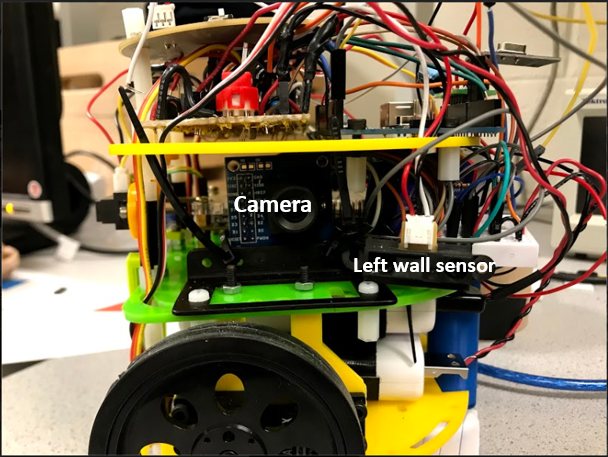
Left Side View of Robot with Camera
The last integral part of the design is treasure detection. This is the most complex part of the robot, and although
we were unable to fully integrate the camera with the robot, we were able to get the treasure detection
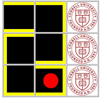
to work somewhat reliably on its own. We needed the robot to detect 6 types of treasures: 2 different colors and
3 different shapes. To determine shape we split the image taken from the camera into three segments: a top
third, a middle third, and a bottom third. We measure the amount of red and blue and lack of green in the image of
these segments. We then threshold and compare the segments to each other to determine the
shape detected.
Final Design
For the final robot, we redesigned its overall layout.
This included both electrical and mechanical improvements. This entire project is
the gambit of the fully autonomous robot using many aspects over many different types
of wired/wireless communications, peripherals, data structures, computer architectures,
and system design. It is the peak of a junior design project. Over the course of four
labs and four milestones, we have programmed our robot how to follow a line, to operate a
servo, navigate with walls, communicate to another arduino, and how to detect color
and think about where to move next. The biggest challenge of it all was to move past
the prototyping stage and integrate an optimized version of the robot with better
power utilization, mechanical dexterity, and algorithmic precision. Although by
competition we were unable to fully integrate our perfected robot, we demonstrated
that our design worked to greatest potential.
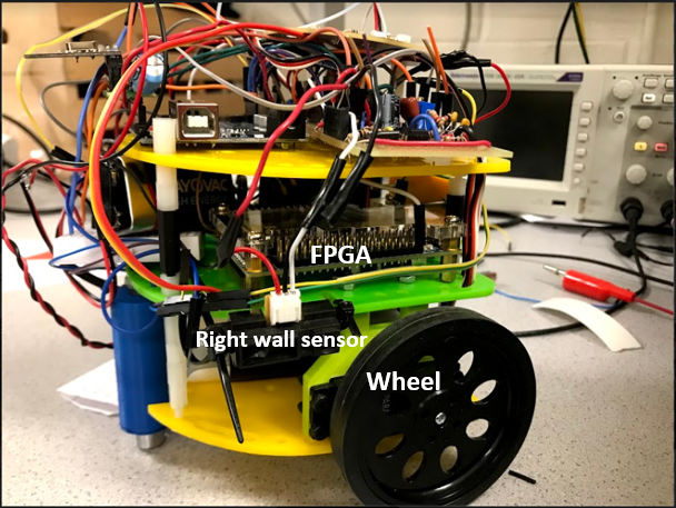
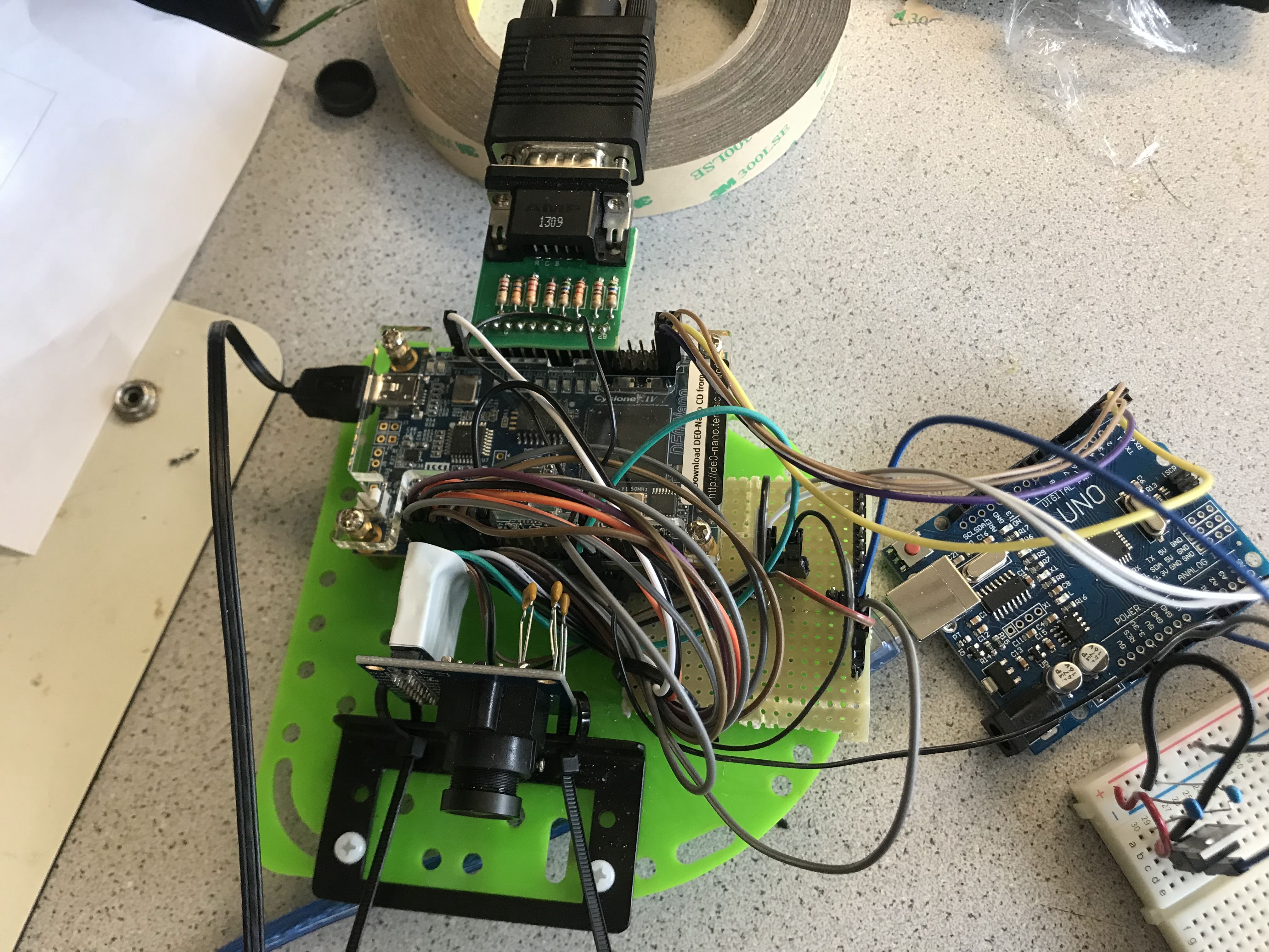
Electrical Hardware
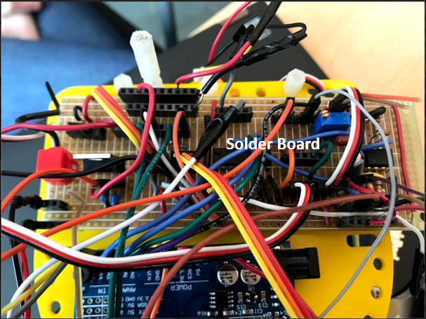
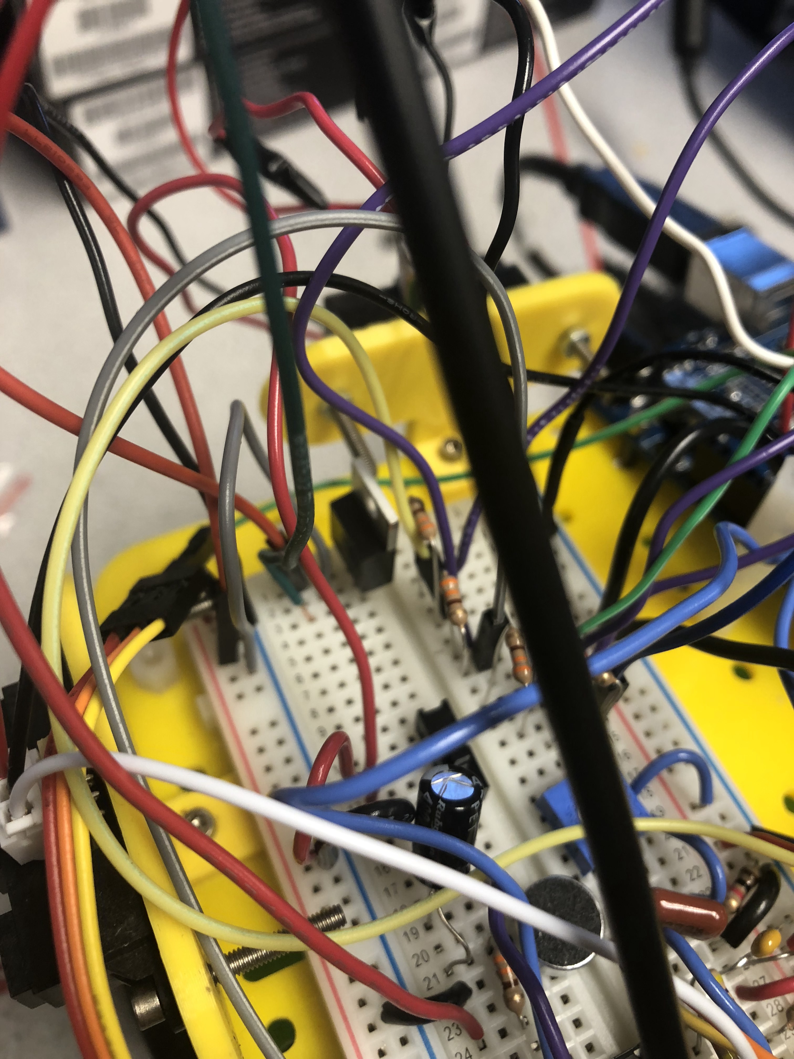
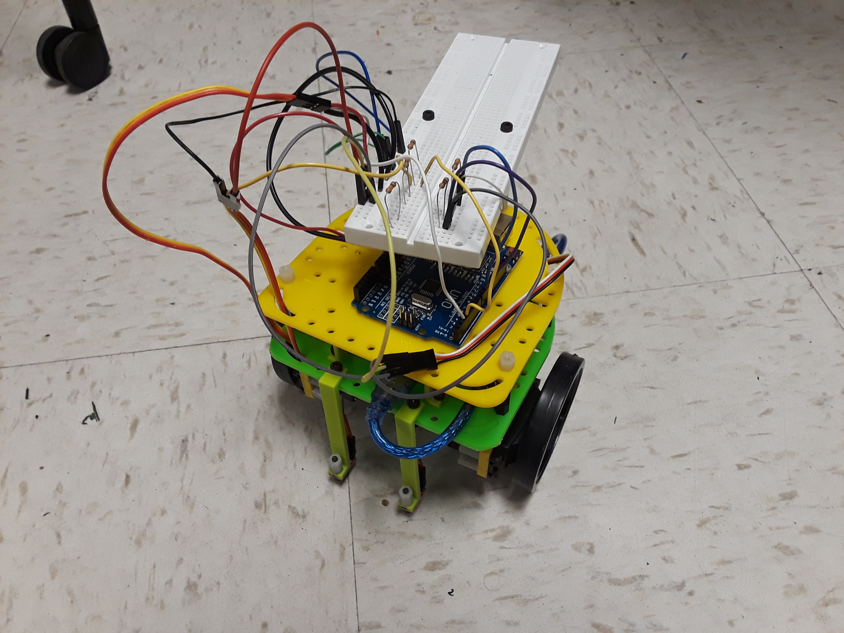
Robot Protoboard
For our electrical hardware, we cleaned up the wiring and replaced the bulky protoboards
with throughput solder board. In order to make the adjustment, we condensed the electrical
hardware for the microphone, the IR sensor, and the Camera controls onto one board and
relegated the hardware to regulate the power to the radio to a smaller protoboard.
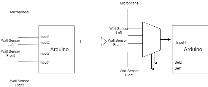
In addition to the new layout, we also decided to optimize power usage and pin layout
by muxing together the three wall sensors and the microphone. Since all four of these
objects can have information retrieved at different times, they don't each need their own pin. So, we used a 4 to 2 multiplexer which takes in 2
inputs and selects between the four signals to input into one pin. We reduced the
required pins from 4 to 3. Overall, we now have power allowance
for each component itself allowing each component to act properly.
This allowed us an extra pin on the Arduino, which was especially useful since we decided to
use parallel communication between the Arduino and FPGA to send treasure information, which required four additional pins on the Arduino. The mux is one implementation to increase the number of pins we have. We effectively trade in
four pins: the selects and output for eight pins which made parallel treasure comunication possible.
The alternative option was to have a serial communication protocol such as I2C style with a clock and
data line where the clock can be driven by the FPGA. However, this implementation would be much more complicated
in terms of software and would need extensive testing to assure reliability.
Powering the robot was a major concern for us because we have a lot of components that drain the power. The two servos, the Arduino,
and FPGA are all major power consumers that can affect the reliability of other sensors since the the consumption may be so high
that it causes the sensors to not be powered fully, affecting their performance. Our solution to this was to use two batteries
and properly balance the load on the battery. We tackled this problem in both hardware and software.
In hardware, we balance the load on the battery by having first battery power the sensors, camera and servos where the servo will be
a hugh power consumer. We use the second battery to power the Arduino and FPGA. We want our processors to have
the best performance possible. In practice, we should have three batteries to fully power everything given the power
consumptions of all of our peripherals since each battery output a max of 1A. In software, we reduce the amount of
unneccessary load on the battery by turning off components that were no used. One example is that we turned off the
line sensors and servo when transmitting to the basestation because the radio consumes a significant amount of power
when transmitting and we simply don't have the power to keep all these components on. Properly powering our robot was
a very important part of design and can mean the difference between peripherals not working and working.
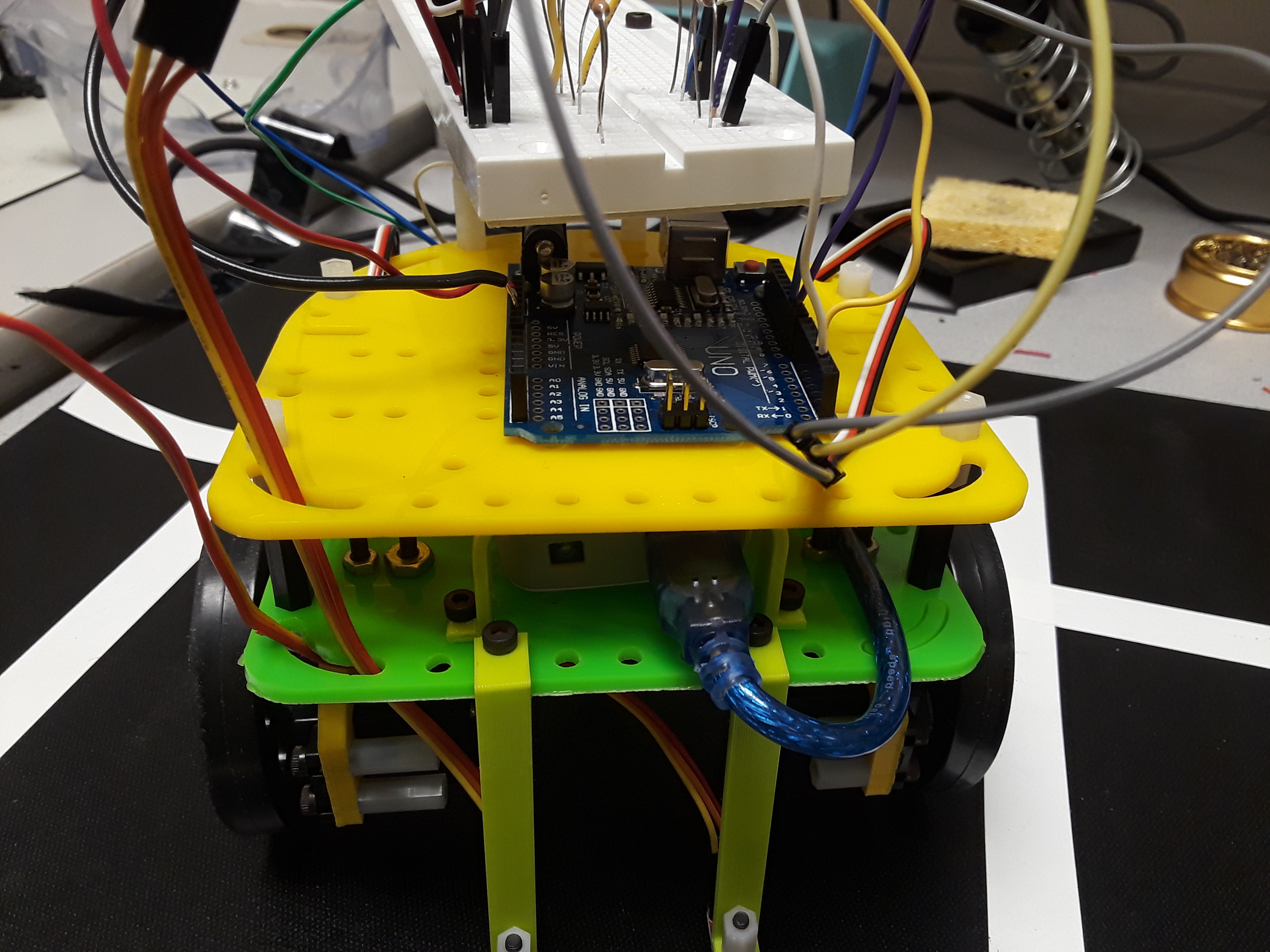
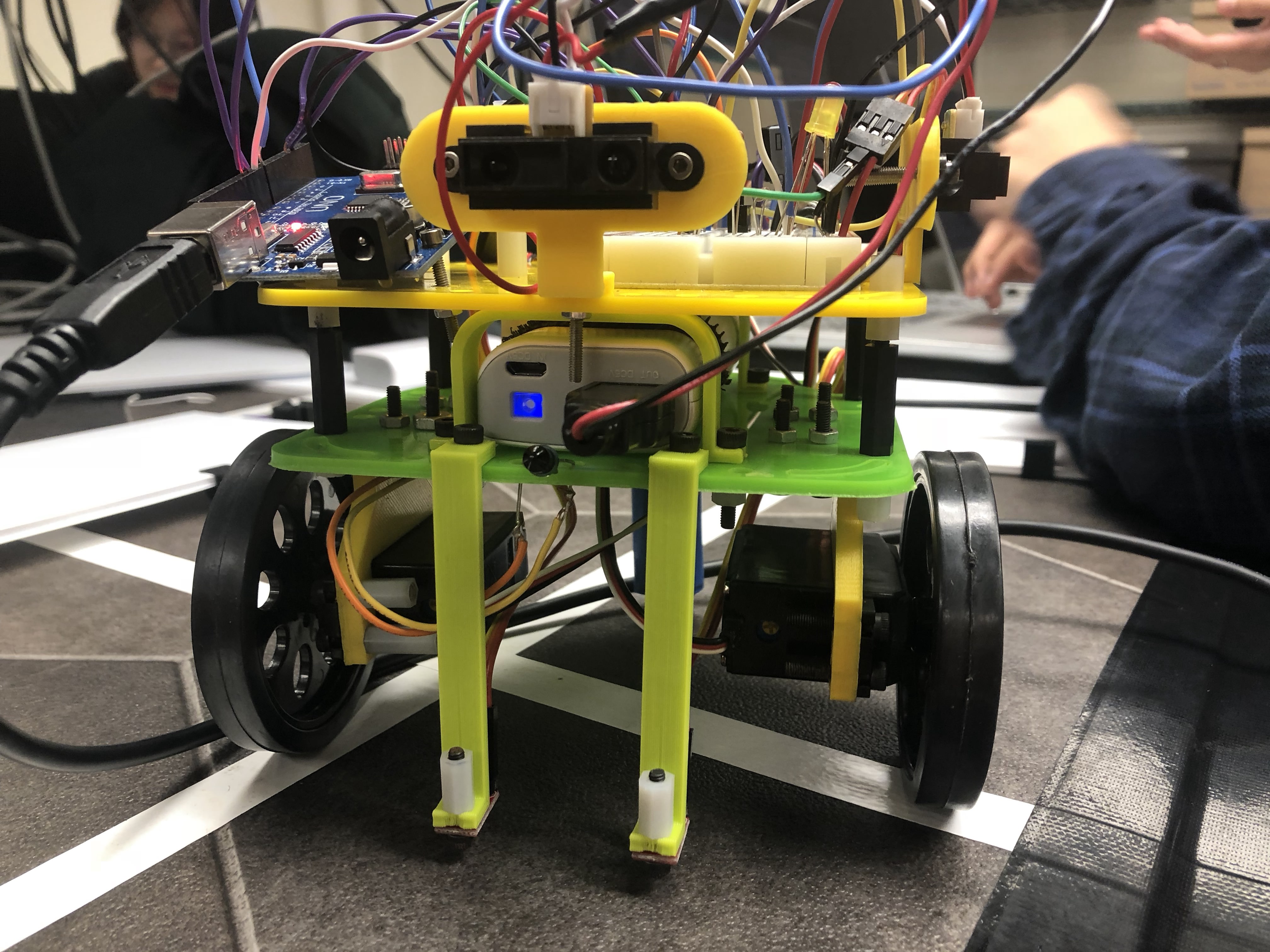
Mechanical Improvements
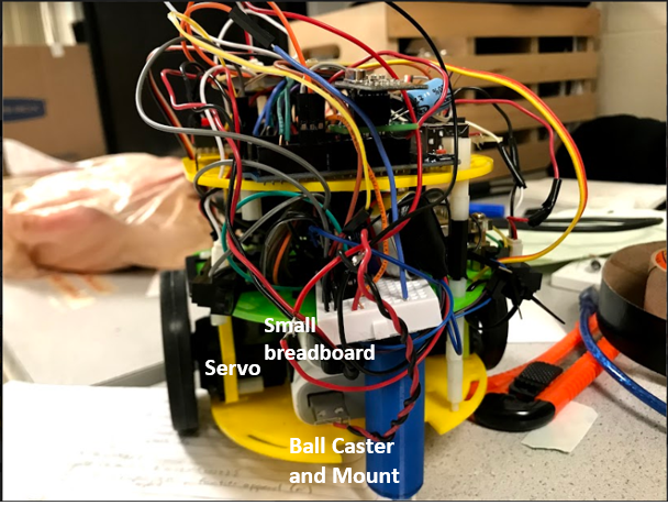
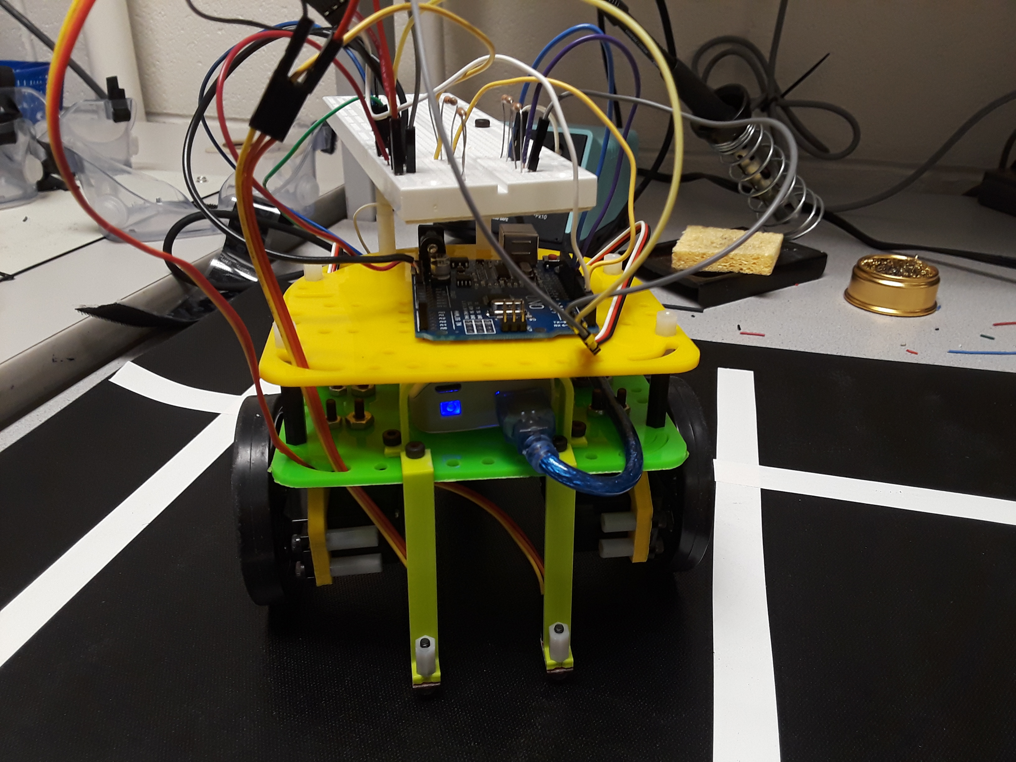
Back View of Robot
We originally had only two layers on the robot. One for the battery and one for the Arduino Uno. However, because
of the addition of the FPGA and camera, we needed to add an additional layer to the robot.
To fit all the components onto the robot, we strategically placed the Arduino,
the FPGA, the Camera, the solder board, the smaller protoboard, and the two battery
packs. We planned a layout with the Arduino and the solder board on the top layer
of the robot, the FPGA, Camera, wall sensors, power regulator for the radio, and
FPGA/Camera connections to the middle layer, and the two batteries to the bottom
layer. To create a layer underneath the robot, we designed and laser cut a base
plate with some chunks cut out of it, allowing room for the line sensors and the
stabilizing appendage in the back. We held it in place by creating two more base
plates with aligned holes for more structural support and flexibility with the
placement of our other components.
As seen in the image above the batteries are at the lowest layer since they need the least amount of adjustment.
To retrieve the batteries, we would have to remove the ball and caster mount, but since the batteries do not
drain quickly, we didn't need to replace the battery often.
The second layer contains the camera and FPGA. The camera had to be at the right height to detect the
treasure placed on the walls. The second layer is the obvious decision. We also placed the wall sensors here
for the same reason. To separate the FPGA from the Arduino. The FPGA contains it's own set of circuits but they
must share a common ground.
The third and top layer contains the Arduino and protoboard. The placement was advantageous for us becase it allowed
us to easily debug the circuit and program the Arudino. We also places the required IR hats here at the 5.5 inch mark. The radio
was also hosted here for best communication reliability.
Cost
Given the supplies that we had used on our root, here's the cost that we have incurred:
Item
Unit Cost
# of Units
Total Cost
Line Sensors
$3
2
$6
IR Distance (Wall) Sensors
$7
3
$21
Camera
$14
1
$14
Parallax Servos
$13
2
$26
Arduino Uno
$16
1
$16
Item
$83
Competition
In the Competition, due to the issues we had with testing and integrating the hew robot design,
we were not able to compete as strongly as we wished. In the first round of competition, one of
the main power supplies died on us. For the second round of the competition, our line sensors
went on the fritz and could only map out 8 squares.
Reflection: If it ain't broke don't fix it
Conclusion and Suggestions for future work
Looking back on the learning experience of building this robot, we have achieved many impressive
results and overcome great challenges, but there are several things we wish could have been different
as well. In hindsight, we made one significantly miscalculated decision that cost us on competition
day: moving from our original breadboard which worked reliably with nearly all of our components to a
soldered protoboard. We made this choice for both aesthetic and reliability reasons, thinking that it
would both be more compact on the chassis and be a more robust design without worries about wires popping
out. In reality, however, we underestimated the time it would take to debug the new circuit. We spent
countless hours the days before competition trying to figure out why components no longer functioned at
all, instead of optimizing our maze navigation, treasure detection, and the overall power plan for our
robot. We believe that otherwise our robot could have given a much stronger performance, and are
disappointed when remembering how more reliably it navigated mazes just four days earlier.
For future work on the robot, definitely the best option would be to implement Djikstra's algorithm
onto it. We have created a data structure that would be able to handle the algorithm, but unfortunately,
we were unable to implement it due to time constraints and complexity. The data structure allowed for dynamic
allocation, and wouldn't have taken up too much space in the heap, but alas, the DFS that we instead implemented
worked well enough.
This project and class was one of high highs and low lows: many long hours in lab between
the Monday night lab section and endless extra lab hours, but great excitement when our efforts
paid off and our robot had new features. We learned important new skills each step of the way,
from FPGA experience to web design to debugging to teamwork. And we built a robot with impressive
number of nontrivial capabilities!!
ECE 3400, FALL 2018 Team 7
Team Members: Patrick Clobridge, Tara Van Nieuwstadt, Xiaoyu Yan, Chrissy Mayer
Team Procedures
Day, time, and place for regular team meetings:
UH142, Friday 11.15-12.05pm, weekly.
Alternate time and place: Duffield, Wednesday 12.10-1.10.
Other times will be considered at discretion.
(We suggest allocating more time towards the end of the semester)
Preferred method of communication (e.g., e-mail, cell phone, wired phone, Blackboard Discussion Board, face-to-face, in a certain class) in order to inform each other of team meetings, announcement, updates, reminders, problems:
Groupme
Decision-making policy (by consensus? by majority vote?):
Consensus
Method for setting and following meeting agendas (Who will set each agenda? When? How will team members be notified/reminded? Who will be responsible for the team following the agenda during a team meeting? What will be done to keep the team on track during a meeting?):
Agenda assignee will rotate among members every four weeks as specified
in the Team Leadership section below. Agenda will be determined by the
designated member before each meeting with input from other members
regarding desired discussion topics. We will be reminded via groupme.
Everyone is responsible for following the agenda. If someone gets off
track, we will guide the conversation back on topic. The person who
created the agenda will be primarily responsible for following it.
Method of record keeping (Who will be responsible for recording & disseminating minutes? How & when will the minutes be disseminated? Where will all agendas & minutes be kept?):
Keep track of records on Google Drive. All documents and reports as
well as meeting agendas and minutes will be disseminated via Google
Drive and Groupme if someone is missing from the meeting. The team
will collectively create a succint summary of what was discussed or
accomplished during the meeting before dispersing; these will be the
meeting minutes.
Team Expectations
Work Quality:
We all want want to perform in this class to our greatest potential. So, we will make sure
that our work is pristine, comments are understandable and well marked, and
generated processes will be well documented for ease of the next user.
Project Standards
Team presentations are to be rehearsed, collaborative writing needs to be peer
reviewed, individual research has to be well documented and thorough, preparation
of drafts should be case by case, where we all understand the purpose, and peer
reviews are to be thorough, no detail left unchecked (We don't want another
Challenger to happen!)
Strategies to fulfill these standards:
Team Participation: Hold each other and yourself accountable for the work done
(Don't let your teammates down, don't mess up the PK!)
Communicate clearly on your expectations. Don't let things that bother you build up.
Strategies to ensure cooperation and equal distribution of tasks:
Keep in mind how much time each task takes, and take into account previous experience,
while at the same time giving people the chance to work on tasks that they are interested in.
Strategies for encouraging/including ideas from all team members (team maintenance):
Listen to everyone's ideas. Have ideas thoroughly developed before each meeting.
Strategies for keeping on task (task maintenance):
Develop task deadlines before each meeting to establish the reality of each deadline.
Keep track of deadlines on Google Drive and place in our calendars.
Preferences for leadership (informal, formal, individual, shared):
shared, informal leadership.
Personal Accountability
Attendance, punctuality, and participation are required, unless if a member has conflicting issues come up.
Attendance, punctuality, and participation are required, unless if a member has conflicting issues come up.
Expected level of responsibility for fulfilling team assignments, timelines, and deadlines:
High level of responsibility for all three.
Expected level of communication with other team members:
Whenever someone completes a task or is having on a task, they should communicate.
Expected level of commitment to team decisions and tasks:
Everyone should be in on decisions and tasks.
Consequences for Failing to Follow Procedures and Fulfill Expectations
Describe, as a group, you would handle infractions of any of the obligations of this team contract:
They are responsible for taking care of agenda for week after infraction.
Describe what your team will do if the infractions continue:
You'll have to keep doing agenda stuff, or we'll bring it up with the Prof.
Team Leadership
Every person on the team will have to take the role as a leader. The role of the leader will be to organize
meetings and make sure that everything is submitted in a timely manner.
(Split up the time according to the number of members, below is an example for a team of 4).
Is "a ban on offensive autonomous weapons beyond meaningful human control" going to work?
In their open letter on the topic of autonomous weapon systems, experts in the field of Artificial Intelligence including Elon Musk and Stephen Hawking warn of the danger a global AI arms race poses to humanity. They call for an international ban on “offensive autonomous weapons beyond meaningful human control,” asserting that this is the only way to avoid a third revolution in warfare. Further unbridled development of the technology would lead to increased instability worldwide once they are amassed by major military powers and available on the black market, exacerbated by how cheaply manufacturable these weapons will eventually become.
While we agree that so-called “killer robots” are incredibly dangerous and could be used for downright evil purposes well outside the Law of War, we do not think it is practical from a security to standpoint to place trust in the effectiveness of an international ban. It would be incredibly irresponsible to stop development of this technology because other major military powers “agree” to do the same. These are weapons of mass destruction, and an unpoliced attack by any military power could be unimaginably deadly.
We would draw a parallel between this issues and nuclear weapons rather than an issue like gun control. With respect to automatic firearms, the argument is often made that stricter gun laws leads to less guns everywhere leads to less deaths due to gun violence. In contrast, due mostly to the magnitude of potential casualties, it does not seem like a similar idea is practical with respect to autonomous weapons, like we have seen with the nuclear arms race.
However, strict regulation is needed as progress continues. At least domestically, it will be necessary to keep close tabs on the researchers working in this area as well as who has access to the details of its development. It is unallowable for obvious reasons to allow rogue programmers to implement this “killer robot” technology. Perhaps a government encryption system could be used to regulate who has access to all existing progress that will be advanced upon. There needs to be a proactive security system robust enough that not just any CS graduate or advanced hacker can implement this dangerous weapon (in the vein of regulating blueprints for the 3D printing of guns).
As has been proven time and again over the course of history, it will be impossible to stop the progress of science in this field. The stakes are high: this issue could grow as significant as that of a nuclear holocaust. Therefore, it is within the best interest of humanity to step ahead of the curve regarding regulation.
Familiarize ourselves with the Arduino IDE and Arduino Uno
Learn introductory Arduino programming and basic Arduino functionalities
Create simple circuits and Arduino programs to explore digital and analog Arduino I/O ports, built-in Arduino functions, and serial communication
Construct our robot and write a program to make it move in a square
Introduction
In Lab 1, we began with using digital I/O pins to make internal and external LEDs blink.
We then used a potentiometer to explore using analog circuits with the Arduino. We started
by simply reading out analog values from the potentiometer on the serial port. Then we used
these values to adjust the brightness of an external LED and the speed of a continuously
rotating servo. The lab culminated in building a functional robot that could drive autonomously in a square.
Blink
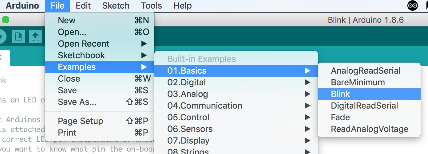
We made the Uno’s built-in LED blink by running an Arduino example code, found as follows:
Blinking LED example code location
The code worked as expected, as can be seen by the
following demonstration of the internal LED blinking:
Serial Monitor and Analog Pins
To experiment with using the serial monitor and analog pins,
we tested reading values from a potentiometer. We connected the potentiometer
to the Arduino by connecting its output to an analog input pin of the Arduino,
and connecting the potentiometer to the Arduino's 5V power and ground. To avoid
accidentally short-circuiting the LED, we also added a 300 Ohm resistance in
series with the potentiometer. We used the analogRead() function to read the
potentiometer values and used the Serial.println() function to print those values
to the serial monitor. These functions are included in the code for the LED analog
output.
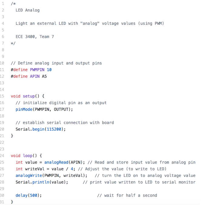
LED Analog Output
Next, we used the analog output from the potentiometer to control the
brightness of the LED. After reading the potentiometer value, we adjusted that value
and used the analogWrite() function to output it to an Arduino pin with PWM
capability (pin 10 in the code below). We had to adjust the output value to be within
the range accepted by the analogWrite() function; the potentiometer readings returned
values between 0 and 1023, and the analogWrite() function accepts values between 0 and
255.
Writing Potentiometer Values to LED Code
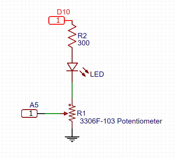
We set up a circuit according to the following schematic, similar to what we
had already set up to read the potentiometer values and adding the connection of the LED
to a PWM pin:
Schematic for controlling LED brightness with potentiometer
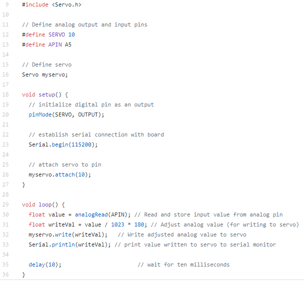
Servo
We used the Arduino analog I/O pins to control the turn direction and speed of
continuously rotating servos. We relied primarily on the Arduino’s servo library to control
the servo. On a high level, we dictated which analog I/O port (PWM pin) would be used to
control the servos and then used the write function of the servo library to dictate the speed
and direction of the servo. We combined the servo with the potentiometer in a similar way to
what we did with the potentiometer and LED, allowing the potentiometer to control the speed
and direction of the servo by adjusting the value read from the potentiometer and writing it
to the servo via a PWM pin (pin 10 in the code below).
Writing Potentiometer Values to Servo Code
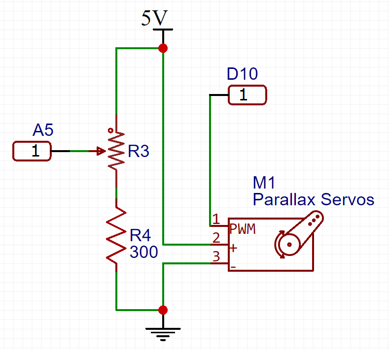
We set up a circuit according to the schematic below, similar to what we had
created for the LED and adding in the servo connection to the PWM pin and the Arduino circuit:
Schematic for controlling servo with potentiometer
Adjusting the potentiometer changed the speed and direction of the servo as we
expected, and as is shown in the following demonstration of servos controlled via the potentiometer:
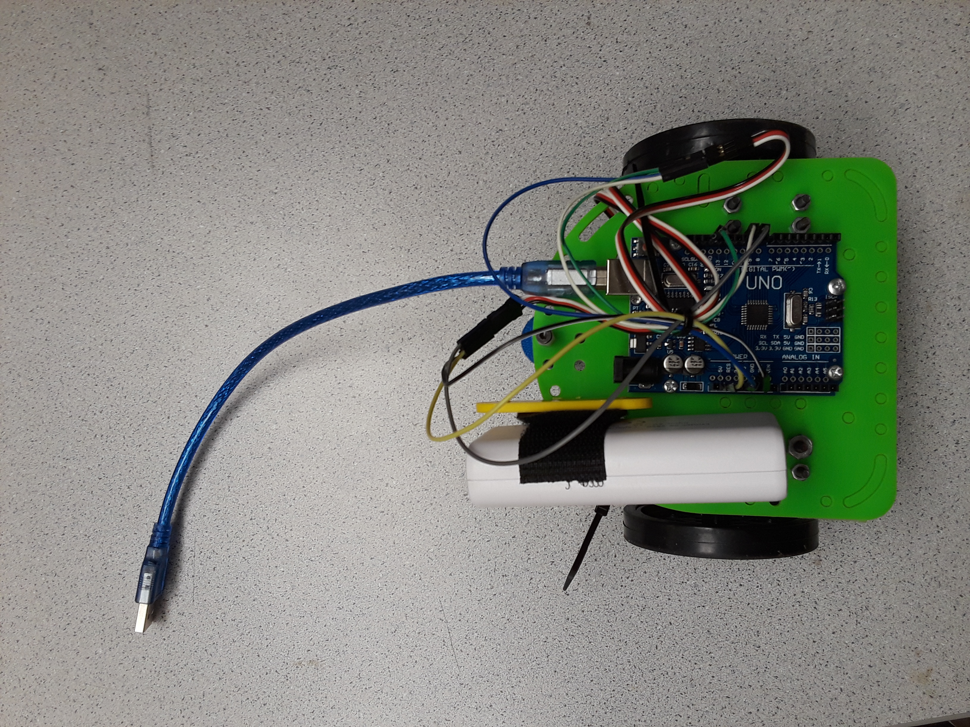
Robot
We built the robot consisting of a chassis and two servos with wheels attached, and mounted
the Arduino on top of the chassis. We also attached a 5V DC phone charging port to power the
robot. Finally, we wrote a simple Arduino program for the robot to drive in a square.
Assembled Robot
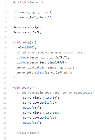
Robot Square Driving Code
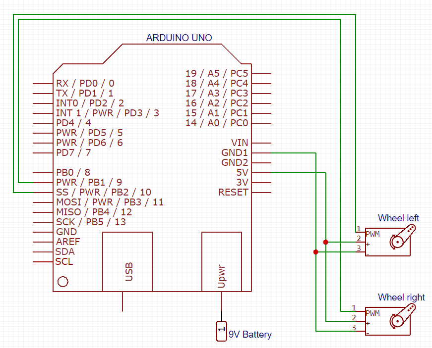
The circuit on the robot is set up according the following schematic:
Schematic for current robot
The robot was able to move autonomously as we had directed, as shown in the following
demonstration of the robot moving in a square:
Conclusion and Result
The robot moved as expected in the square and there were no problems with the speed of the servos.
However, we did encounter a problem with the direction of one of the motors. The orientation of the
two motors was inconsistent so the right and left wheels spun in opposite directions. This slightly
complicated the code to direct the robot, requiring a roundabout solution even to go in a straight line.
In the next lab section, we will fix the installation of the wheels by reversing the orientation of one
of the wheels.
Implement 6.08kHz IR signal detection, ignoring decoys
Introduction
In lab 2, we added hardware sensors and signal processing capabilities to the robot.
We split into two subteams, with Tara and Chrissy working on acoustics and Xiaoyu and
Patrick on optical sensing. The start of our final maze will commence with a 660 Hz
whistle blow, so the acoustic team used an Electret microphone and an amplifying circuit
to detect the tone and distinguish it from background noise. The optical group used an
IR transistor to detect other robots emitting IR at 6.08kHz, and ignore decoys (18kHz).
FFT Analysis
The “Fast Fourier Transform” is an operation that uses the Discrete Time Fourier Transform
in a time-efficient method to sample a signal over time and return its frequency components.
Because both sub teams had to implement algorithms to detect specific frequencies in a noisy
environment, we began the lab by familiarizing ourselves with the Arduino Open Music Labs FFT
library in order to allow us to use digital filters to process these signals. We each
installed the library in our Arduino IDE and studied the example script fft_adc_serial,
with the goal of understanding how to use the FFT library and identifying the frequency
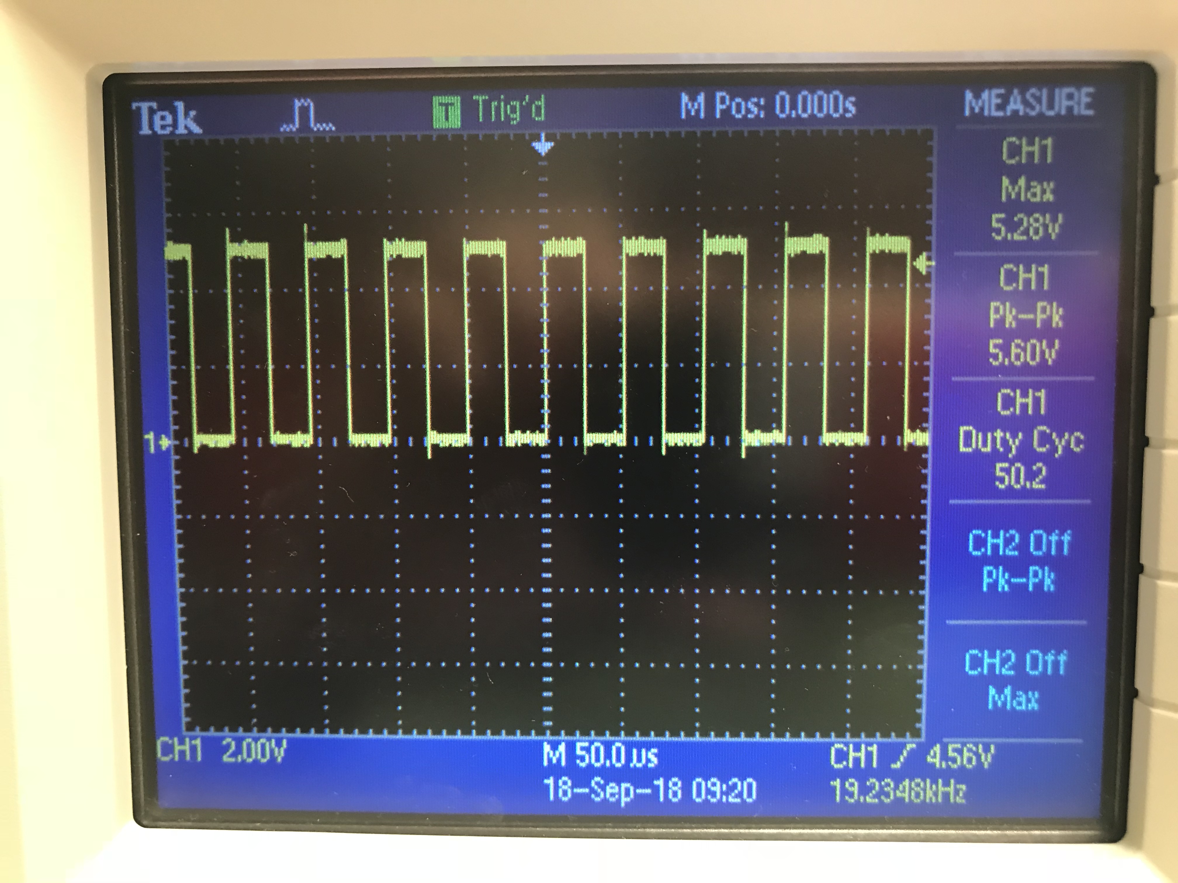
bin where we should look for our signal. First, we looked at the sampling frequency of
the ADC. There are two ways to identify this rate -- the first is to use the oscilloscope
and the digitalWrite() function to change the state of the digital pin whenever the ADC
finishes one conversion. The scope will then measure the frequency of the output wave.
Based on our implementation, we know that the ADC converts two values per period, so the
frequency is about 38 kHz.
Frequency of the ADC
To confirm this result, we referenced Section 28 of the ATmega328 datasheet, which provides
information about the ADC. It indicates that the last 3 bits of the ADC Control and Status
Register A determine a prescalar by which the Arduino clock frequency is divided to determine
the ADC clock frequency. The example script fft_adc_serial sets this division factor to 32 in
the second line of the code snippet below. Given the 16MHz Arduino system clock frequency and
the 13 clock cycles it takes the ADC to convert, we used the formula (Arduino clock cycle /
total conversion clock cycles / prescalar) to find the 38 kHz sampling frequency.
Calling the FFT function is simple using the Music Labs' library where we first must setup the ADC settings:
ADMUX =0x40;// use adc0
ADCSRA =0xe5;// adc prescalar
The FFT libraries takes care of the actual calculations of frequencies from the analog input to FFT outputs.
We had to take the necessary samples for the library to calculate:
for(int i =0; i <512; i +=2){// save 256 sampleswhile(!(ADCSRA &0x10));// wait for adc to be ready
ADCSRA =0xf7;// restart adc
byte m = ADCL;// fetch adc data
byte j = ADCH;int k =(j <<8)| m;// form into an int
k -=0x0200;// form into a signed int
k <<=6;// form into a 16b signed int
fft_input[i]= k;// put real data into even bins
fft_input[i+1]=0;// set odd bins to 0}
fft_window();// window the data for better frequency response
fft_reorder();// reorder the data before doing the fft
fft_run();// process the data in the fft
fft_mag_log();// take the output of the fft
Once this is down we can grab our data using fft_log_out
which hosts the stored data in bins with a specific frequency range per bin.
Acoustic Team
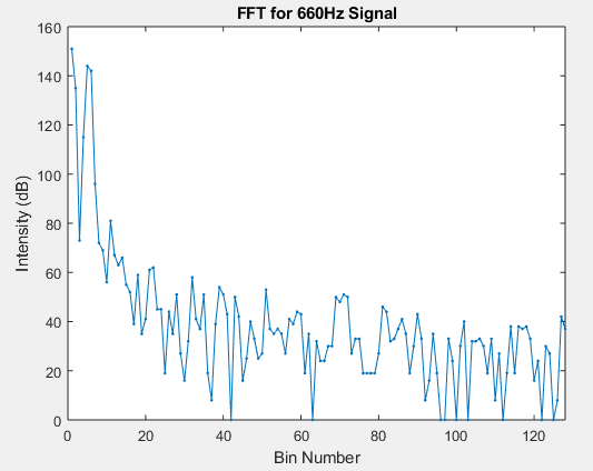
From our analysis of the FFT and our determination of the frequency bin width,
we determined that our 660Hz audio signal should fall in the fifth bin. We
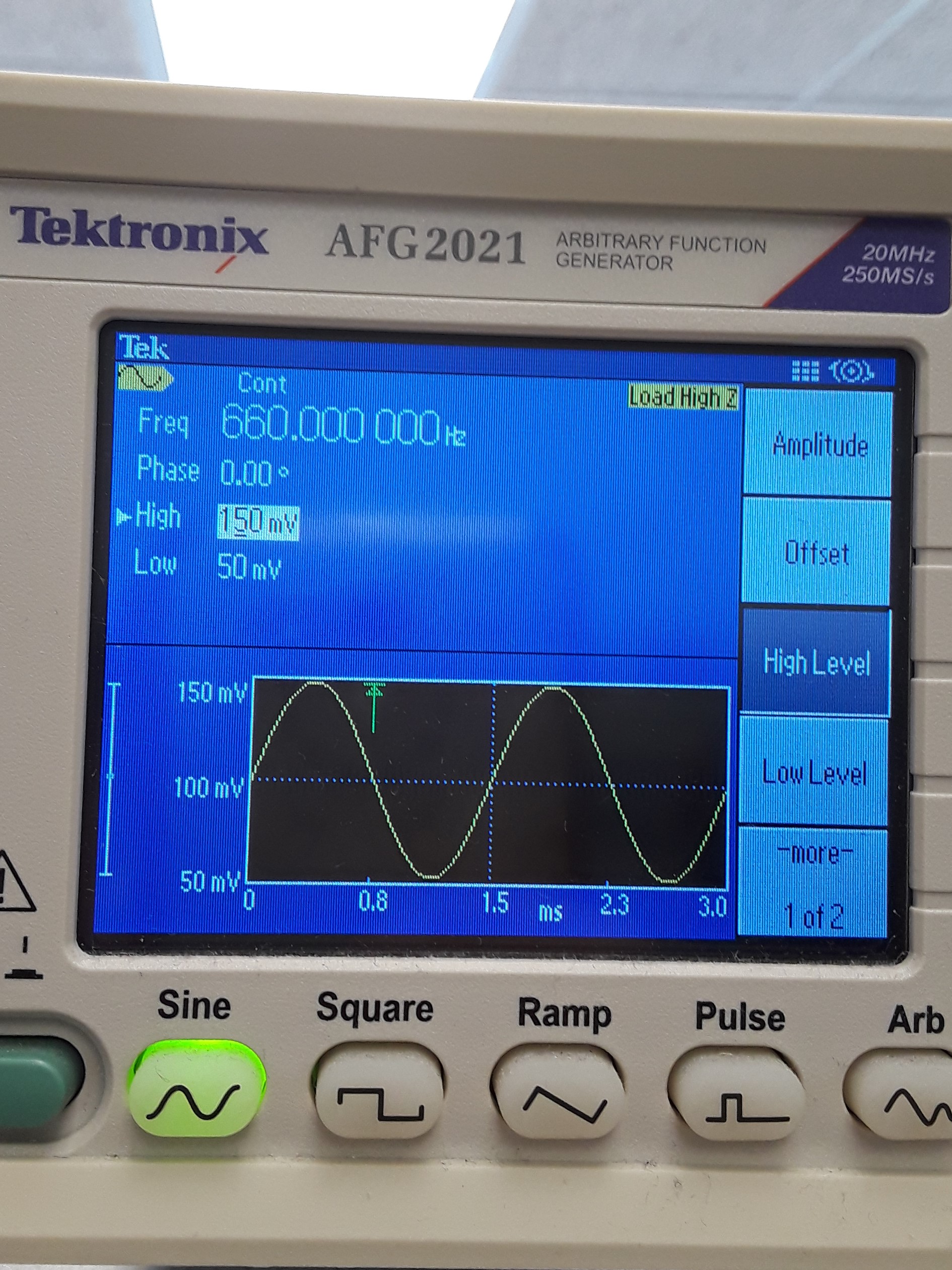
confirmed this by inputting a 660Hz sine wave from a function generator through
a 330-ohm resistor into an analog Arduino pin and running the example fft_adc_serial
code. We graphed the FFT output, as shown below. From this graph we saw our expected
peak in the fifth bin.
FFT output from fft_adc_serial example code with 660Hz Signal from Function Generator
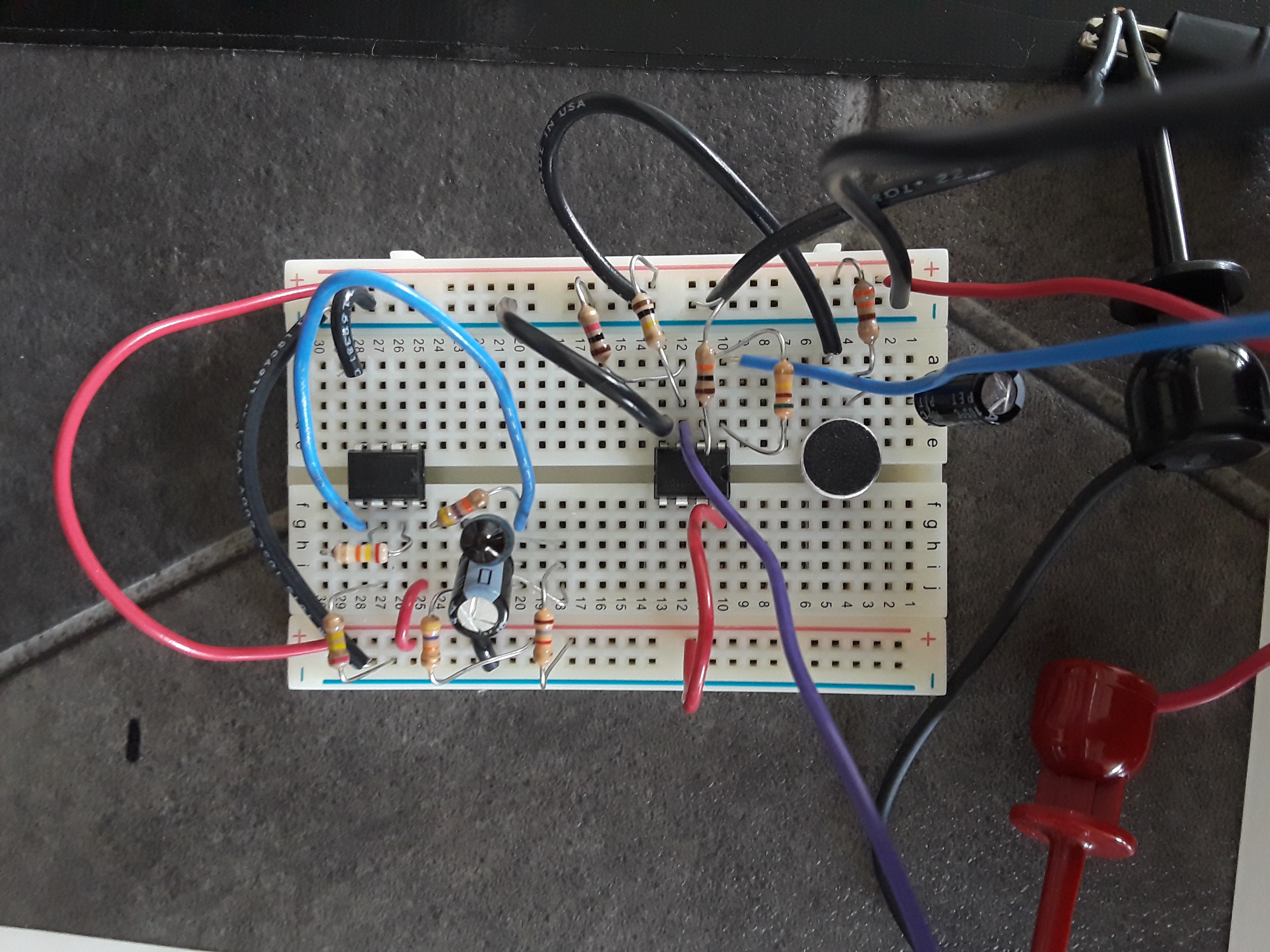
Next we created the simple microphone circuit from the lab document:
Basic Microphone Circuit from Lab Document
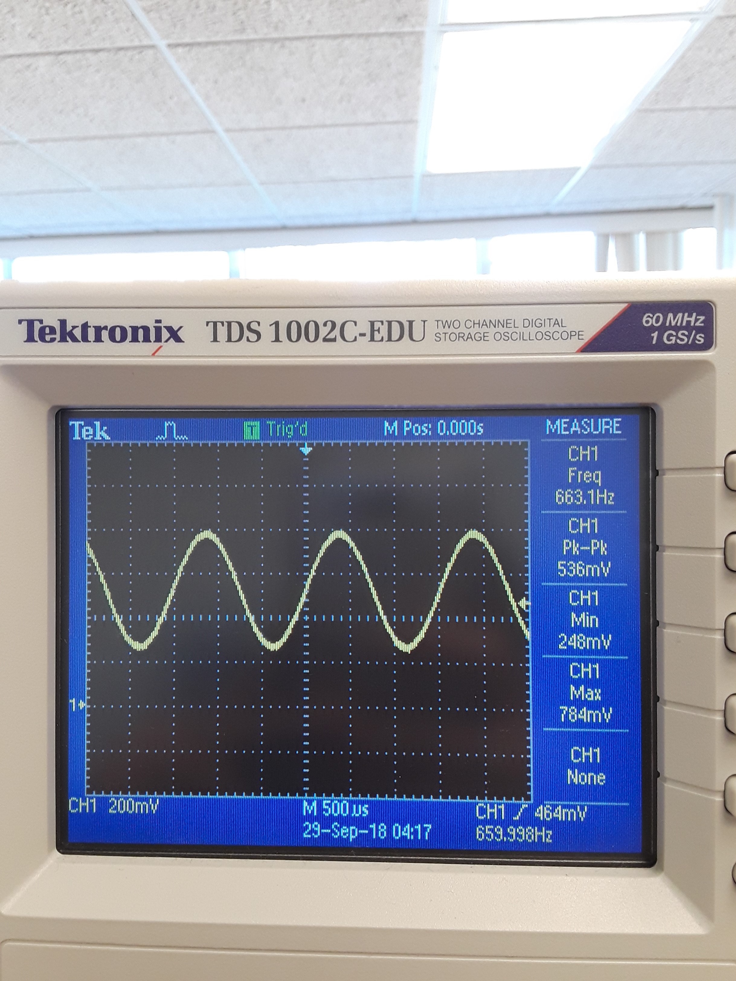
Although we had trouble getting any signal out of the microphone at first, we eventually
were able to see a response on the oscilloscope when we played a 660Hz tone near the
microphone from a tone generator on our phones. We observed that the amplitude of the
signal was around 40 mV, and the output was unsteady and weak.
To amplify this signal to a more detectable and readable value, we created a simple
non-inverting amplifier, starting with a modest gain of around 5 to be safe. We first
tested the amplifier with an input signal from the function generator, reading the output
on the oscilloscope. For a while we were not able to obtain any output signal at all.
After switching our op amp from an LF353 to LM358AN, the amplifier worked as expected;
we saw the desired output and amplification.
We then put the microphone output through the amplifier. We again were not able to obtain
any output signal, so we re-examined our connection between the microphone and amplifier
and added a DC bias. Rather than send the simple microphone circuit output straight into
the amplifier, we decided to keep the capacitor from the example circuit to remove its DC
offset, and use a voltage divider to create a small, 50mV bias at the input to the amplifier.
This allowed us to control our DC offset and left room for a large amplification. After
solving this problem, we successfully increased our amplification to around 52. We played
the 660Hz tone near the microphone and read the output to the scope to confirm that the
signal was what we expected it to be. Our final design was the following amplifier circuit:
Acoustic Amplifier Circuit Design
Finally, we connected the output from the amplified microphone signal to an analog Arduino
pin and ran the FFT code. For clarity, we plotted only the bin 5 output on the serial plotter,
and watched it spike when we brought the 660Hz tone near the microphone. In an effort to
filter out more ambient noise, we narrowed the bin frequency width by changing the prescalar
for the ADC clock input to 128. This was done by changing the ADC Control and Status Register A:
ADCSRA = 0xe5;
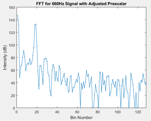
Re-calculating the frequency bin width we determined we should find our 660Hz frequency in bin 19,
and we confirmed this by running the FFT and plotting the results:
Acoustic Amplifier Circuit Design
As a finishing touch, we created a placeholder “robot start” function by lighting an LED whenever
the 660Hz tone was detected, which we did by setting a threshold intensity value for bin 19 as shown
in the following code:
A demonstration of this detection is shown in the following video:
Optical
Initial Design
We used the OP598A phototransistor to detect IR signals. The phototransistor was built exactly
like the schemamtic from the lab, with a 1.8k reistor connected to 5V power supply and the
photoresistor connected to ground. We first put that output into the oscilioscope and got the
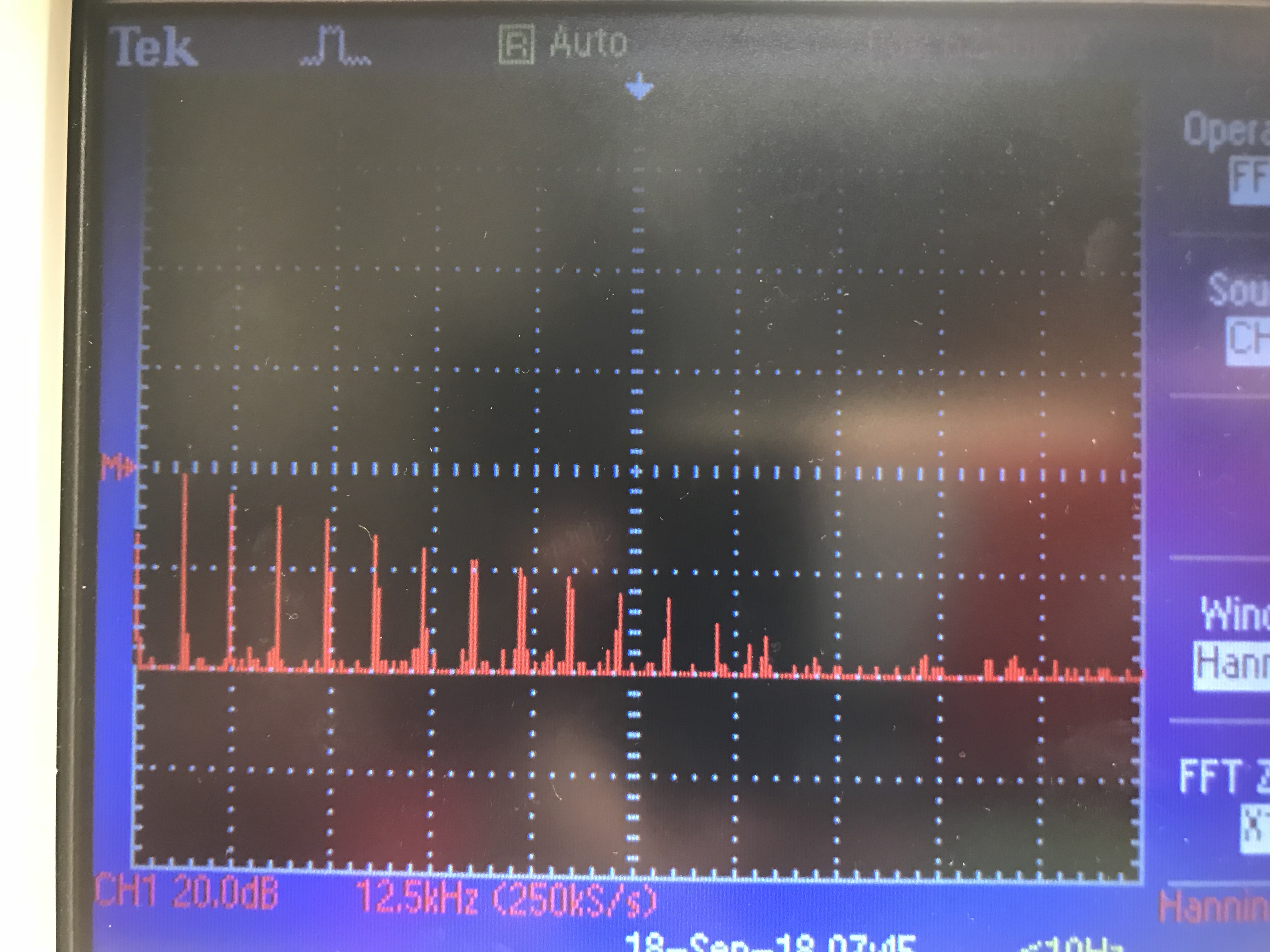
following reading for FFT:
Oscilloscope FFT of IR Sensor without augmentations
The result is from turning the IR hat near the sensor. The signal strength appears to be pretty
strong as there are clearly readings at the 6kHz mark and all its harmonics. For the Arduino,
we used FFT library from Music Labs' FFT. With the library, we can check the intensity of a desired
frequency range to see if the it recieved any signals. We chose a 256 point FFT with a known ADC
sampling frequency of 38.5kHz. Therefore, each bin of the FFT has a frequency range of Fs/N or
around 150Hz per bin. Thus the 6.08kHz desired frequency is located at bin 40. Thus, all we have
to call is
fft_log_out[40];
to get our readings.
Upgraded Design
The signal strength of the FFT at our desired bin was already strong but we wanted to implement
noise filtering which means we need a filter. We also want to amplify the values in order to
utilize all 10 bits of the ADC for a higher resolution reading. The Arduino Analog input can
only take in voltage values from 0 to 5 volts which means that any the input voltage can’t be
negative or higher than that which will result in cut off and possibly damaging the circuit.
Thus, this is the resulting schematic:
Schematic of IR with OpAmp and bandpass filter
We opted with using a high pass filter to remove any DC bias inherent in the output of the sensor
because the DC bias is already high at around 4v. We then amplified the filtered signal by a factor
of 20 which can be adjusted as needed. The amplification seems like a good amount based on the
detection strength of the IR sensor. After we amplified the signal, we ran the output through a
low pass filter that removes any high frequency noise and harmonics. We chose the values of the
capacitor and resistor such that the bandpass filter contains a lower cutoff frequency of 5.5kHz
and higher cuttoff frequency of 6.5kHz. The formula to calculate the cutoff frequency is 1/(2*pi*RC).
This completes our bandpass filter.
Testing
For testing we started with unit tests by turning on the hat and holding it a certain distance from
the phototransistor and check the output of the FFT printing to serial. We also implemented a blinking
LED that would increase blinking rate as the IR gets closer to the phototransistor. The frequency of
the blink rates tell us how close the hat is to the IR sensor. This tells us that the sensor is working
as intended. In the video, the blinking is from the Arduino's internal LED although we should have used
an external instead for demostration purposes.
We also reedited the FFT library's codes to record FFT values in a single FFT cycle for better side by
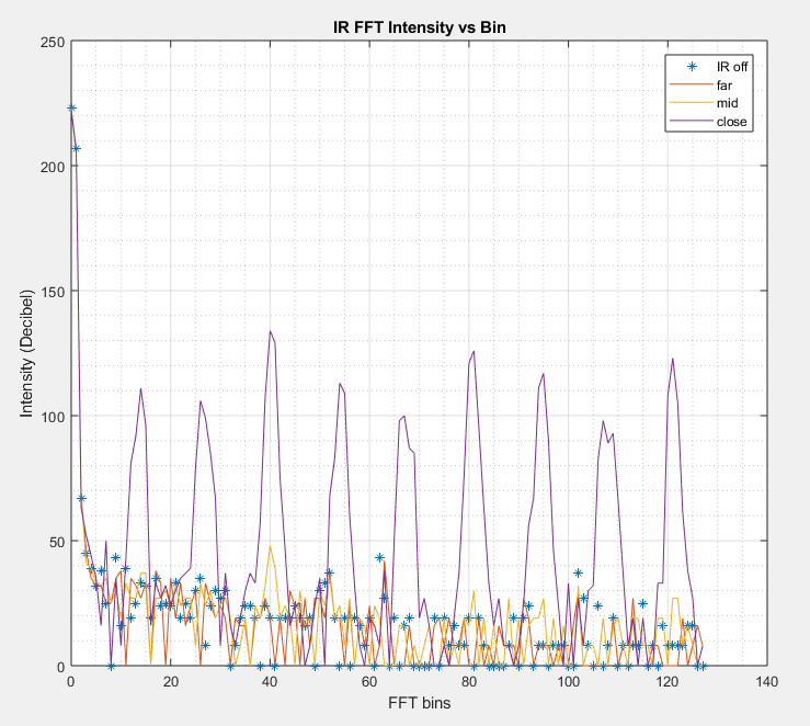
side comparison. Here are the results:
We divided the tests as such:
off: IR hat turned off
far: IR hat 1.5 intersections away from sensor
mid: IR hat 0.5 intersections away from sensor
close: IR hat right next to sensor
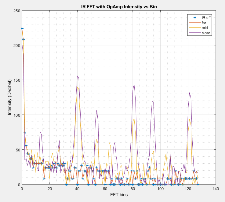
FFT of IR without Op Amp FFT of IR with Op Amp
From these two comparisons, we can see that the op amp increases mid range performance of the IR sensor
by detecting more of the IR hat's correct frequency signal whereas the harmonics appears to be more
filtered out as a result of the installed bandpass filters. The long range performance appears to be
unaffected by the augmentation and the close range performance clearly increased slightly.
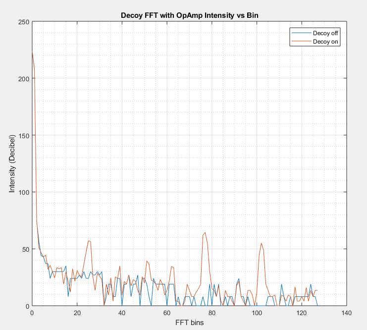
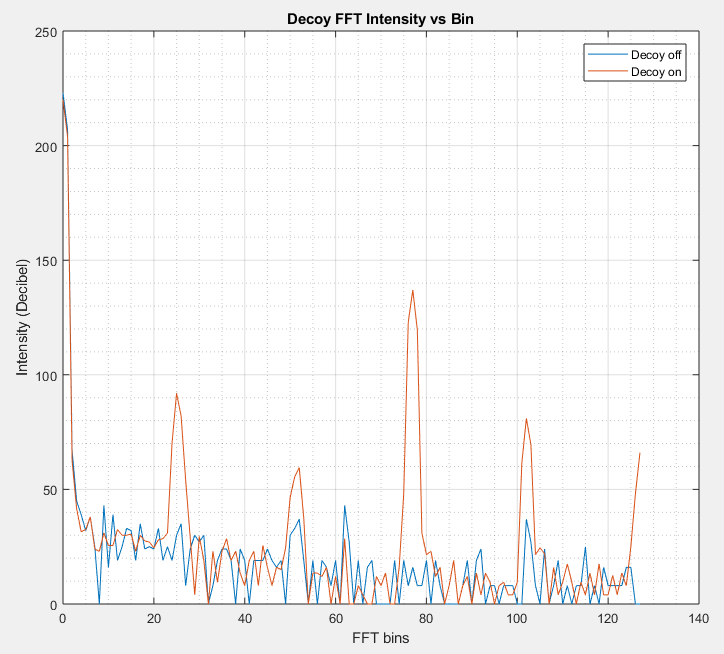
After testing that the sensor could detect the desired signal, we then tested the robustness of our
filtering software and hardware by giving it decoy signals. We used a decoy IR signal at around 12kHz
placed next to the sensor and read its FFT's. We also used the decoy to test our sensor for detecting
different frequencies.
FFT of Decoy FFT of Decoy with Op Amp
We reached two conclusions with this test. The augmented sensor worked with different frequencies because
the signal strengths were clearly amplified. Although for this test, it appears some of the noise were
amplified as well but it was not significant. We also see that the 40th bin of the FFT is contains only
background signals. This means that the signal strength will not be enough for the threshhold to detect
a false positive. With these two tests, we proved that the IR sensor's hardware and software can detect
the desired frequency amount and augmented it so that it detect farther away signals.
Integration
The IR sensor and microphone together!
To integrate both the optical and the acoustic sensors, we first read input from the acoustic sensor
through pin A0. Once we get a hit from the acoustic sensor, we switch to reading input from the IR sensor
at pin A1. Both of these inputs rely on the same FFT function.
In order to properly incorporate this, we have put in a 5-part finite state machine. The state starts.
It then moves on to recording and running the FFT on the audio. Once we record the audio, we go to
process it. If the bin containing 660Hz passes its intensity threshold (meaning we've detected the
tone and we need to start), we start recording IR. If not, then we go back to recording audio. From
here, we continue to recording and running the FFT on the IR. If the IR surpasses its threshold
(meaning a robot is detected), it writes to the serial monitor and goes back to the start. Else, it
keeps recording IR.
enum states{
START,
AUDIO_FFT,
AUDIO_PROC,
IR_FFT,
IR_PROC
};
uint8_t state;void loop(){switch(state){case START://check point
state = AUDIO_FFT;//next statebreak;case AUDIO_FFT:
ADMUX =0x40;// use adc0/* Some FFT array from ADC generating code.... */
state = AUDIO_PROC;break;case AUDIO_PROC:/* Processing FFT result code and check threshhold... */if(past_some_threshhold){
state = IR_PROC;//past threshhold so we move on}else{
state = AUDIO_FFT;//recalculate FFT with new samples}break;case IR_FFT:
ADMUX =0x41;// use adc1/* Some FFT array from ADC generating code.... */
state = IR_PROC;break;case IR_PROC:/* Processing FFT result code and check threshhold... */if(past_some_threshhold){
state = START;//past threshhold so we move on}else{
state = IR_FFT;//recalculate FFT with new samples}break;}}
Conclusion
We were able to integrate both the IR and microphone sensors to a single code base. This step is
important as we will need to integrate all of the code from the different modules we made into the
arduino. Looking forward, we would like to increase the ranges of the microphone sensors and IR
sensors such that they will be able to detect the correct freqencies from farther away. This is
important since the IR is used to detect other robots and the microphone is used to start the robot.
We also want to explore ways to schedule our code because the sensing is a hard real time process
where we have to stop the robot if it is in danger of collision and thus, we must find a way to
quickly calculate the FFT and then have the robot react quick enough. A likely solution will be
to use interrupts.
Design an efficient data scheme to store all maze information on an Arduino
Familiarize ourselves with Nordic radio transceivers and the RF24 Arduino library in order to communicate between radios on two different Arduinos and send maze information wirelessly
Communicate with the GUI and update it from a wirelessly connected Arduino to display explored vs. unexplored areas of the maze
Fully integrate all components onto the robot so it starts on a 660 Hz tone, explores the entire maze, stops if it sees another robot but ignores decoys, and displays maze information on the GUI via radio communication with the base station
Introduction
For this lab we integrated all of the robot’s capabilities that we had previously implemented into a cohesive system that communicates wirelessly with the provided GUI. We first worked on creating an algorithm that would efficiently store all the information our robot detects as it navigates through the maze. Next, one subteam (Patrick and Chrissy) worked on adding the radio component to the robot, setting up the two Nordic nRF24L01+ transceivers that we would use to communicate wirelessly between two Arduinos, one on the robot and one on a base station connected to the GUI. Meanwhile the other subteam (Tara and Xiaoyu) integrated all the robot’s other functionalities: starting on detection of a 660 Hz tone, line following, wall detection, and detection of other robots while ignoring decoys. At the end of the lab we combined all of the work so that the robot can autonomously explore the maze and update the GUI in real time.
Radio
For the radio portion of the lab we implemented two Nordic nRF24l01+ transceivers. To test out the connection between the two radios, we ran the example “GettingStarted” code on two separate Arduinos with radios attatched, ensuring proper communication. After that, we integrated other radios onto the "base station" (an Arduino connected to a computer) and the Arduino on the robot. Since the Arduino does have a 3.3V power supply, we needed to implement a 3.3V voltage regulator for each radio to step down to the appropriate power. This adjustment from our previous strategy, using 3.3V from a DC power supply, made the radios more portable.
Coding the radio involved setting the correct pipes to send our messages through the radio. Our team was assigned pin values const uint64_t pipes[2] = { 0x0000000014LL, 0x0000000015LL }; to avoid conflicts with other teams' radios. The transmitter writes to pipe 0x14 while reading from pipe 0x15; the receiver reads and writes the other way around. The RF24 library abstracts many of the complexities of radio transmission so that we only need to call some prewritten functions to send messages with the radio.
To transmit, we call radio.write( &buff, sizeof(buff) ), where the buffer can be an integer.
After writing, the transmitter has the option to hear back from the receiver, as shown in the code shown below. This allows us to confirm that the radio has delivered its package correctly, as well as send feedback between the robot and the base station.
[2:0] We reserve three bits for detecting walls. The position of the walls
will be relative to the robot.
bits[2:0]
Wall Locations
000
left_wall, front_wall, right_wall = false
001
left_wall = true
010
front_wall = true
011
left_wall, front_wall = true
100
right_wall = true
101
left_wall, right_wall = true
110
left_wall, front_wall = true
111
left_wall, front_wall, right_wall = true
[5:3] We reserve three bits for the treasure since there will be three shapes and
two colors, giving us four options, and we also need to define when there is no
treasure. Total, we have five options.
[7:6] The direction the robot has decided to take after hitting the intersection
bits[7:6]
Directions
0
forward
1
right
2
left
3
reverse
[8] Robot detection
[9] Valid message
[15:10] Reserved for potentially later usage. Allows filled with zeros.
The one byte communication message that the base station sends back to the robot is structured like this:
[3:0] Three bits for whether the relative locations next to the robot has
been explored or not
[7:4] Reserved for later usage. Allows filled with zeros
The message sent back to the robot allows the robot to make decisions based on the state of the maze. The robot can make decisions based on whether the locations near it have been explored or not. This can affect which direction the robot turns in an intersection. This comes at a cost of implementing additional decoders for the robot on the system.
Simulating the Robot
To simulate the robot on the base station, we take the information that the robot sends and structure it into a format that the GUI can pick up.
Base Station-to-GUI Transmission
We simulated the base station to GUI transmission by using print statements in the base station. The base station receives messages from the robot and decodes the message with the absolute directions in North, West, East, and South. The base station also prints out any detected treasures. The base station uses both the robot's wall sensor values and the direction the robot decides to go to determine the next square where the robot will be. Then it uses the robot's facing direction to figure out the absolute position on the maze. We always start our maze with the robot facing 'right'. As the robot moves through the maze, we update the GUI one intersection at a time.
This is the decoder we used to get all the necessary values. We use the wall directions in combination with the direction the robot decided to take to update the robot's position on the maze for the GUI.
To update the robot's absolute position in the maze, we use the direction the robot is facing and where the robot decide go towards in the intersection to up date the robot.
Code snippet for updating the maze locations.
case forward://forward : robot decided to go forwardif(robot_direction==right){
x++;}elseif(robot_direction==left){
x--;}elseif(robot_direction==up){
y--;}elseif(robot_direction==down){
y++;}break;
Once the logic is set in place, we print the required values to the monitor so that the GUI can pick it up. We call ```python main.py COM# --rows 3 --cols 2``` for a 3x2 maze
GUI of the 3x2 Maze
There is a missing wall that the robot hasn't explored wall yet because the robot starts facing away from the wall.
Robot Integration
The robot subteam’s task was to integrate all the pieces we’ve been working on into one cohesive system. A fair amount of this had already been completed for Milestone 2. What remained was to add the functionality to starting at a 660 Hz tone, as well as sending signals between radios to the base station. We also had to integrate all the necessary hardware onto the robot.
Adding the Radio to the Robot
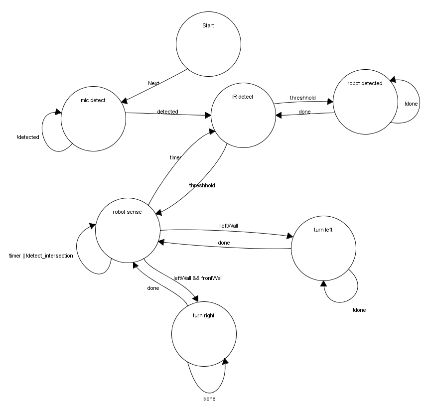
Robot State Machine
State Machine for the Robot
Integration with Mic
In order to make the robot start exploring the maze when we play the 660Hz tone, as it will in the actual competition, we added the audio portion of lab 2 onto the robot. We moved the circuitry and microphone onto the robot’s breadboard and connected the output signal to the Arduino.
We had previously been having trouble with the range of our 660Hz tone detection -- the microphone was only able to distinguish it from background noise when we played the tone from our phone's speaker about an inch away. We learned that if we unplugged the power from our wall sensors our results improved significantly, presumably because this gave more power to the microphone and allowed it to better pick up audio signals. To solve this problem, we decided to move the microphone power to the arduino, while keeping the wall sensor power on the main breadboard circuit powered by the battery.
Robot Navigation through the maze
Since we had already implemented a left-wall-following rule in milestone 2, our navigation implementation was already complete, and we did not have to change any of our code involving our wall and line sensors or turning conditionals.
Integration with Radio
For the integration with the radio, we decided to do most of the decoding and data processing on the base station and off the robot system because we are already running low on memory and we can delegate some of the maze processing to the base station and have it send back a response. The robot only needs to send the readings from its wall sensors, treasure detection, and direction it intents to move. The base station will take the data and come up with absolute coordinates and wall locations based on robots previous locations. The base station can then update the GUI accordingly.
Conclusion
Overall, Lab 3 proved to be quite a challenge. We learned a lot about wireless communication, bit optimization, and integration and testing. With the addition of new components, we needed to better optimize the circuit layout on our robot and the power supplies for each component. Through the frustration of component faults and other issues, we’ve learned how to better debug our problems.
Use a camera and FPGA to implement a system for detecting treasures
Develop an FPGA module capable of detecting shapes and colors from a camera input
Communicate treasure detection from the FPGA to the Arduino
Display images from the camera onto a screen
Introduction
For this lab we began working with an FPGA to implement treasure-detection capabilities
for the robot. The system consists of an FPGA, a camera, and an Arduino. To divide the
work for this lab, Patrick and Chrissy worked with the FPGA, and Xiaoyu and Tara worked
with the Arduino. The FPGA team worked on implementing PLL, downsampler, and image
processor modules in Verilog for the FPGA, and the Arduino team worked on writing to
appropriate registers in the camera in order to set it up properly for taking images.
The two teams then came together to integrate the components to take image input from
the camera, send the images to the memory of the FPGA and process the image to detect
shape and color, and then send treasure information from the FPGA to the Arduino so that
the robot can finally send that information back to the base station.
FPGA
First, we implemented a phase-locked loop to clock the FPGA.
Using the provided Verliog project, we set up the interface our system would use for shape detection.
Setup
We first use the PLL, which is not suceptible to clock skew, to produce different clocks
to drive the camera, VGA, M9k block memory read and write. We use the 24 MHz clock to drive
the camera and plug that as XCLK. We use the 50 MHz clock for memory write and 25 MHz clock
for read. We want write to be faster than read because writing to the block needs to be done
before we read. We don't want to accidentally read blocks before they are updated. We also
use the 25 MHz clock for VGA display.
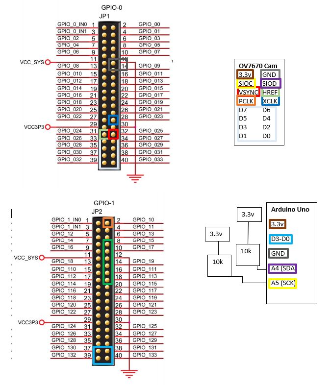
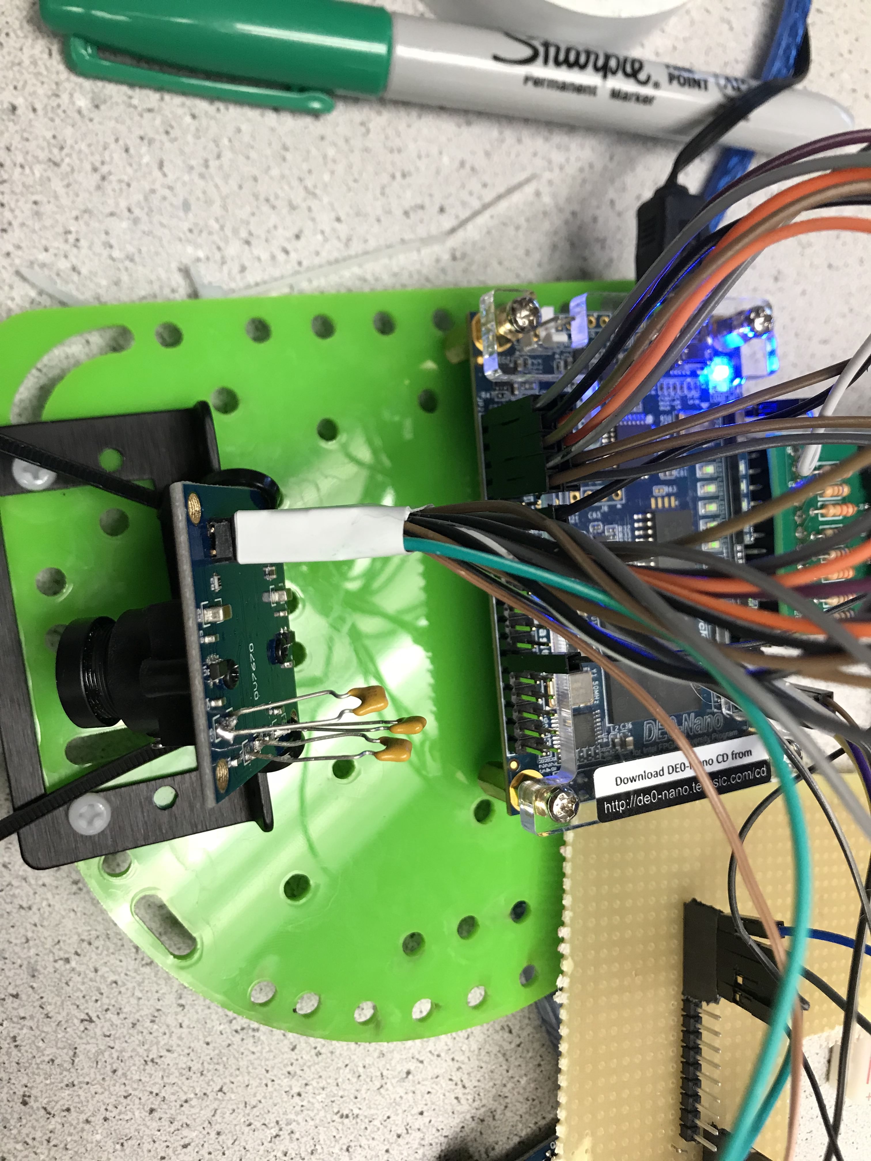
Camera, FPGA and Arduino Communication
The camera contains 20 pins total. We have 8 pins for parallel data which sends one of the two
bytes for pixel during each clcok cycle. These eight pins are connected to input GPIO pins on
the FPGA. In addition, we also have HREF and VSYNC pins which are also connected as input to the
FPGA. The camera also has PCLK and XCLK pins. The XCLK is for external clock. We use an output pin
from the FPGA and put it to the camera. The PCLK is camera clock; we route that back to the FPGA for analysis.
Wiring Diagram for FPGA, Arduino Uno, and Camera
In the figure above, the colored rectangles mean that the pins are wired together.
In the FPGA, we must set the camera communication pins, HREF, VSYNC, and PCLK to
input for the FPGA. We set the the communication pins with the Arduino as output.
In quartus, this is done as follows:
//////////// GPIO_0, GPIO_0 connect to GPIO Default //////////output[33:0]GPIO_0_D;//////////// GPIO_0, GPIO_1 connect to GPIO Default //////////input[33:20]GPIO_1_D;
We also use four parallel wires for communication from FPGA to the Arduino. We have
two bits for treasure shape and two bits for color.
Polling from camera
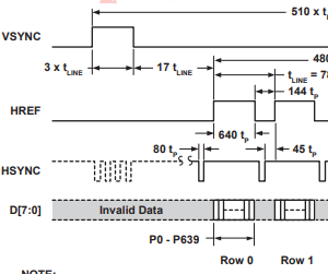
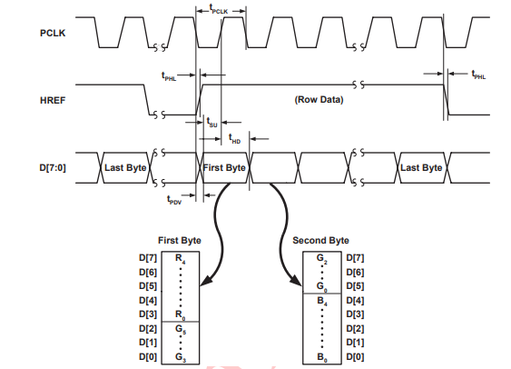
Timing Diagram for the OV7670 camera
The above timing diagram shows us how images from the camera are sent. When we have
a new frame incoming, the VSYNC goes high. After some time, the HREF will go high,
signalling the start of the first byte of data. The camera can send data in RGB565
which is 5 bits of red, 6 bits of green, and 5 bits of blue color. This is divided
into two transmissions due to the camera's one byte communication line. When the HREF
goes high, the camera is transmitting the data for the first row of data. A low HREF
means that we finished transmitting data for one row. At this point, the VSYNC can go
high to signal the end of the image or the HREF can go high again when the camera is
sending data for the next row of pixels.
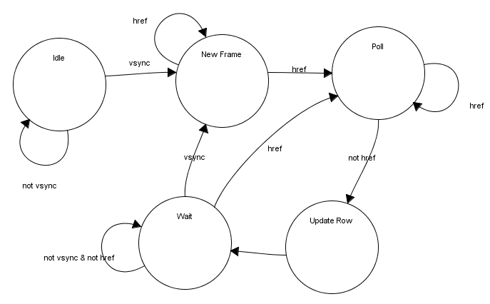
FSM for getting data from camera
Based on the timing diagram, we created this state machine to model the behavior of the camera transmissions.
States
Function
IDLE
Start of device. We wait here for camera to start
NEW FRAME
Start of new frame where we reset the X and Y address
POLL
Enable to downsampler and poll from camera
UPDATE ROW
New row of pixels. Update Y address and reset X address
We must save the data from the camera into a memory location
so that it can be read by the VGA and the image processor
later for analysis. This is done with two variables, X_ADDR and Y_ADDR.
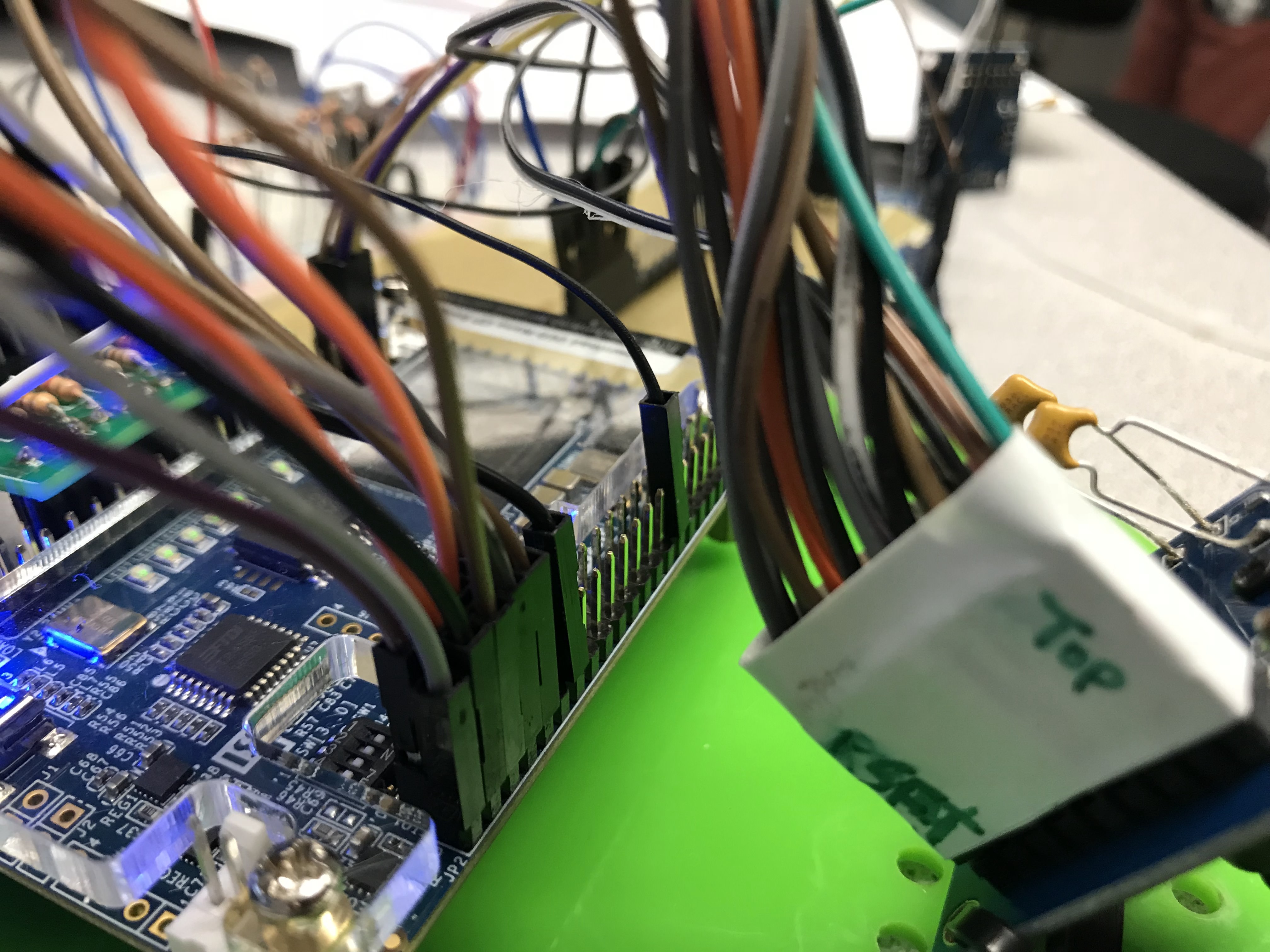
Camera Connection to FPGA
Downsampler
The camera's eight parallel data pins output color per pixel at a clocked
rate. For RGB, it uses the configuration for RGB565 or RGB555. Both
configurations are two bytes in length total which means that each pixel
captured by the camera are two bytes. We must downsample the two byte data
from the camera to 1 byte data because of memory constraints on the M9k
memory blocks on the FPGA. We can only store one byte of data per memory
address. Thus we must convert to RGB332 or RGB323. We used RGB332 for
debugging and displaying the camera data on the VGA screen since the VGA
only takes in RGB332 values. For treasure detection, we changed to RGB323
to get more bits out of the blue pixel since we are only detecting blue and
red treasures. The goal of the downsampler is to take the two byte pixel
from the camera and converted it to a one byte pixel. This one byte pixel
will be saved into the M9k memory block at the correct memory address which
is relative to the pixel location on the screen.
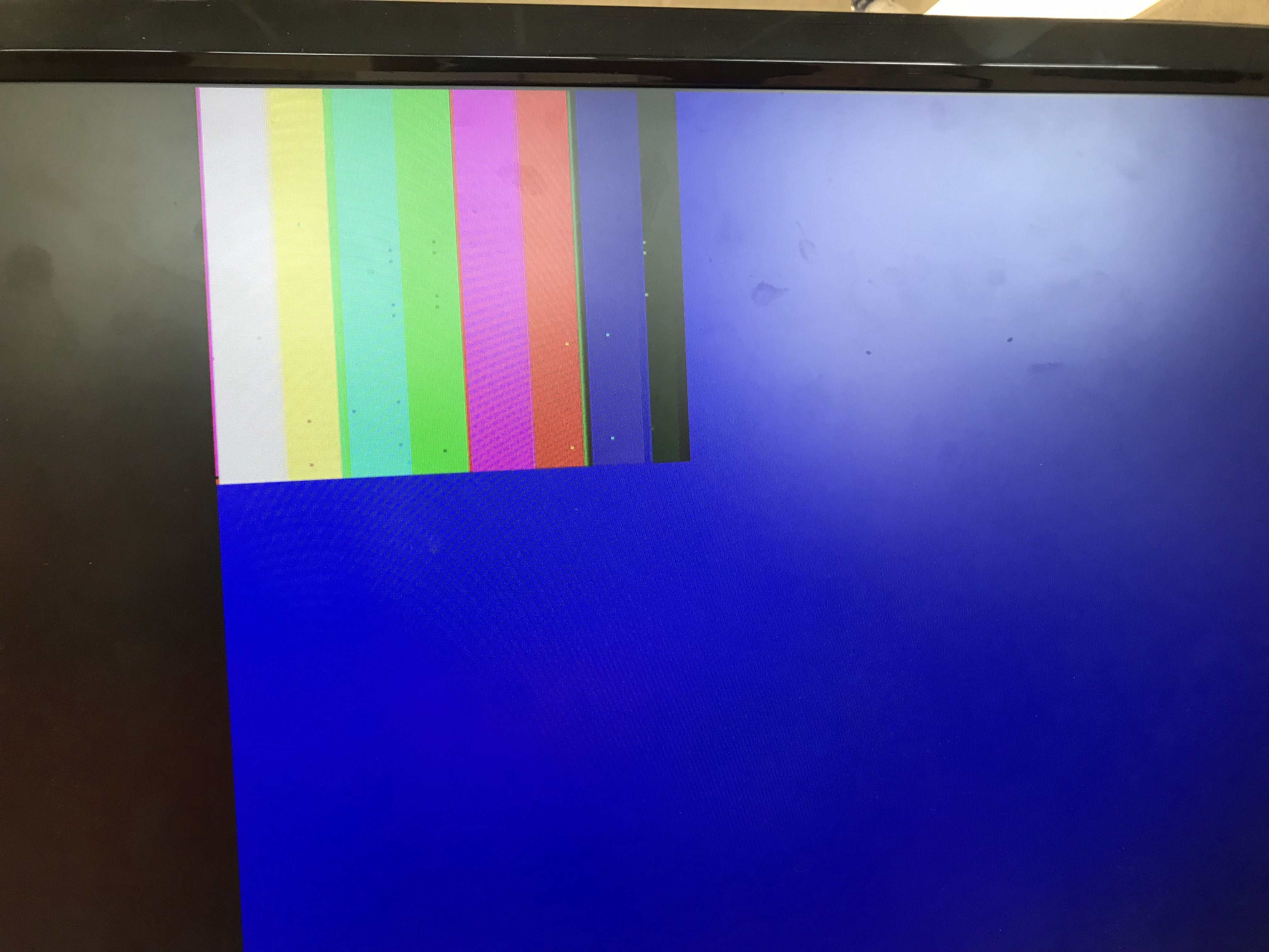
Timing Diagram for Outputing RGB565
To display the color bar, we must set the appropriate registers
in the Camera. The main registers involved are COM 7 and COM 17
for color bar enable and color bar DSP enable. With the downsampler
above, we are able to decode the bytes coming from the camera and
display the color bar onto the VGA screen. The downsampler takes
in input from the camera.
Color Bar Test
The colors in the bar are different from the example in the lab but when
we use the camera to capture, we found that the colors were passable and
would not pose an issue.
Display Camera Capture
To display the images captured by the camera, we must set the registers from
the Arduino. We can disable the DSP for color bar and the color bar test itself.
The FPGA code is exactly the same.
Color Detection
For color detection, we use a module call the Image Processor. The image processor
samples at the same rate as the VGA board at 25 MHz. We set a boundary within the
resolution of each image and then count the amount of blue and red in each pixel.
This implementation use a lot of variables. We needed a counter
for the three colors. We used the counter to count the values of
the blue and red pixels if they are within a set of boundary.
The boundary was used as a filter so that we can get the values
that are near the center of the camera screen since that was where
the shapes are most likely going to be. We judge as soon as the VGA X
and Y axis exit the high threshold which means that we are approaching
the end of our image. As shown above, we compare the counters of red
and blue pixels and see if one is greater than the other by some threshold.
We need the green counter because if the green counter is high while
red and blue are also high, it likely means that we are viewing a
white wall since there are no green color shapes. The judging only
occurs once which was done by a flipping bit. We also reset the counters
for the next frame.
Overview of FPGA and Camera
Arduino
Disabling Arduino's Internal Pullup Resistor
In the prelab, we determined what registers we needed to set and what values
we needed to set them to in order to properly set up the camera to do what we need
it to. Before starting anything, we disabled the internal pullup resistors in the
Arduino’s I2C interface so as not to damage the camera by sending 5V to it. We
then downloaded the provided Lab 4 Arduino template in order to use the functions
provided in it to write to and read from registers in the camera.
This is done by going to the Arduino library on our hard drive. This is done by going
to twi.c at C:\Program Files (x86)\Arduino\hardware\arduino\avr\libraries\Wire\src\utility
and commenting out
//activate internal pullups for twi
digitalWrite(SDA,1);
digitalWrite(SCL,1);
This will allow the I2C interface to communicate with the camera without sending 5v to the camera.
Writing Registers
We use the I2C communication protocol to talk to the camera. This is setup using Arduino's
Wire library which supports I2C interfaces. We set up the Arduino as the master and the camera
as slave. The camera has a set slave address of 0x21 after we ignore the least significant bit
because that is used to distinguish between read and writes. The *Wire* library already set this
up for us. All we have to do is pass the upper seven bits of the slave address of the camera to
the I2C interface. We write to the camera by calling:
The library makes it super simple to communicate with the camera using I2C.
To have the camera capture the images we want, we must set some registers on the camera that deal with resolution,
and camera clock. The following shows how we wrote to the registers:
Reset regs; enable/disable color bar test; sets QCIF 176x144 resolution
0x0c
COM3
Enable scaling
0x14
COM9
Auto gain ceiling 2x; Freeze AGC/AEC
0x40
COM15
Max output range [00] to [FF]; Use RGB 565
0x42
COM17
DSP color bar enable
0x11
CLKRC
Use 24 MHz clk from FPGA; pclk can be as high as xclk
0x1E
MVFP
flip and mirror image
We set the camera to QCIF resolution which is 176 x 144 screen size.
This is the smallest resolution the camera supports. We use this
resolution because we lack memory to store any larger sizes on
the FPGA. For the first part of the lab, we tested the camera
and our FPGA polling code by using the camera color bar to make
sure we can display the correct colors on the VGA screen. This
means we have to set COM7 to display the color bar and enable
DSP color bar in COM 17. The other important setting is the
camera clock. This camera clock determines the rate a which each
pixel is sent to the FPGA. We drive the camera with the 24 MHz
FPGA clock. This gives the camera the ability to go up to 24 MHz
for pixel transmissions.
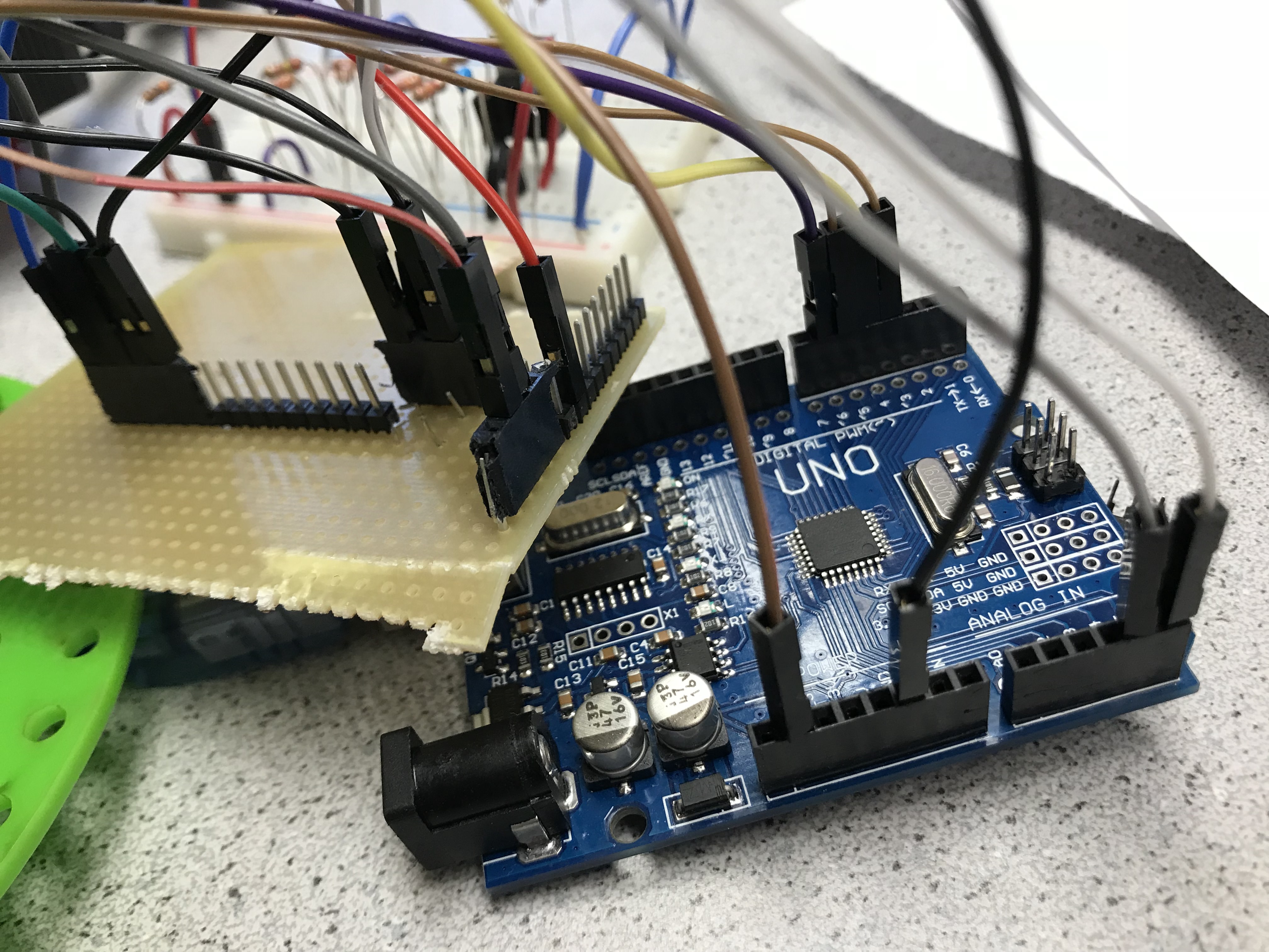
Setup of the Arduino and FPGA
Communicating with FPGA
Communication with the FPGA is done by wiring the GPIO pins on the
FPGA to the arduino in parallel. We use combinational logic in this
case since we set the FPGA to output the results of the image
processing immediately while having the Arduino constantly decode
the message for the four pins. Even though the voltage of the
Arduino pins are 5V while FPGA pins are 3.3V, we can connect
the pins together without a voltage divider because the Arduino
pins are set as input and are capable of reading the 3.3V from
the FPGA as high.
Initially, we define the input communication pins on the Arduino
and the decoding treasure numbers.
This code is the decoder for communication from the FPGA.
The code is very simple because of the extra hardware used.
With this method, we used up to four pins from the Arudino.
We could have used a serial communication protocol using two
pins to send the four bits of messages but we have extra pins
from the Arduino left over so simplicity at the cost of
hardware was prioritized.
Conclusion
This lab is one of the harder labs this semester. Getting the camera to
display an image correctly was a challenge due to the complexities in timing
the camera pixel transmission correctly. While getting the image itself wasn't
too difficult to display, getting the right colors for the image was difficult.
We often had inverted colors or colors that were too dark or faded displaying
on the screen. Both hardware and software contributed to the difficulty. We had
to set the software to poll the bytes from the camera correctly but also had
to ensure sure we wired the camera to the FPGA in a way that wouldn't introduce
noise, especially with a 24 MHz clock driving the transmission. Looking forward,
we will be integrating the FPGA camera system into our robot. This will likely
result in more states and updates to our radio messages to support communicating
treasure shapes and colors. We also will need to update the basestation so that
it can receive messages from the radio.
The goal of this milestone was to implement line-following functionality
to enable our robot to both follow a straight line and trace a figure-eight
pattern. To accomplish this task, we added IR sensors to the robot and
implemented code for it to follow the lines and turn as directed at intersections.
Hardware Upgrades
We spent a large amount of lab time changing the structure of the robot chassis.
The goal is to build a good foundation for the robot structure so that we have enough space
and organization later on as the robot becomes more complex.
Chassis Upgrade
We added a second level to the robot’s chassis to support our battery, the arduino,
and a breadboard for our circuits. This second level allows us to mount the battery in a secure
place and creates room for additions. The spaces between the two levels can also be used to store
wiring for future additional sensors and circuitry.
Front View of Robot after Adding a Second LevelTop View of Updated Chassis
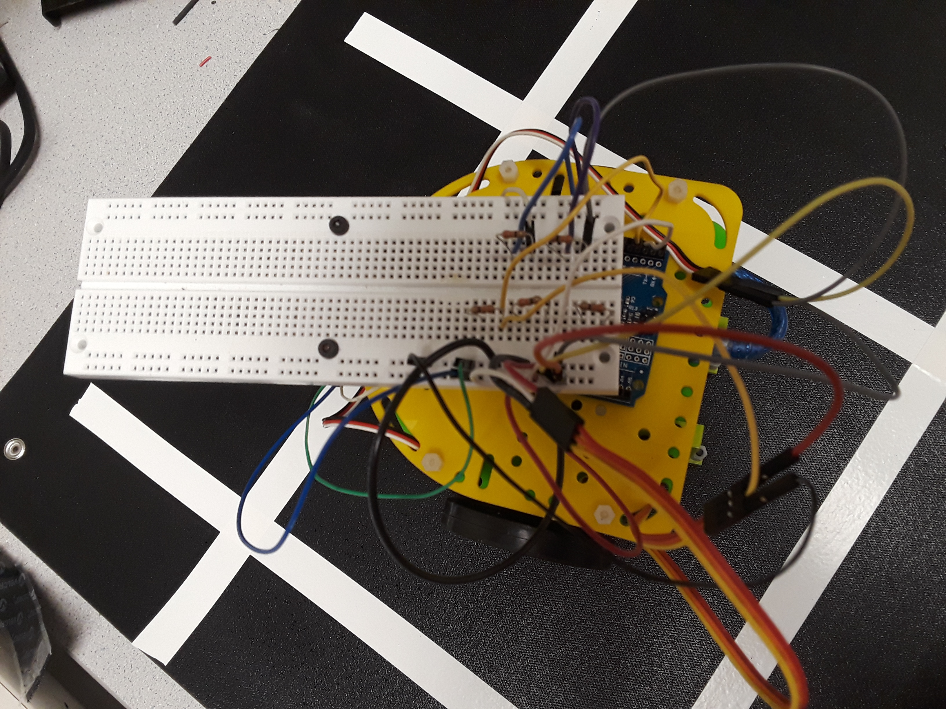
Robot with Breadboard on Top
Adding the breadboard allowed us to create common power and ground lines and connect more
components than there are power and ground pins on the Arduino. We were then able to connect the line
sensors to the Arduino. The current breadboard is temporary, as smaller breadboards were unavailable
during the lab. We plan to attach a smaller breadboard or potentially solder breadboards in order to
securely and reliably attach electrical components to the board. We also plan to attach the breadboard
more securely to the chassis, and will organize the wiring better especially as we add more components.
Line Sensor Update
We used QRE1113 line sensors, which work by transmitting and then detecting IR light that reflects back
to a phototransistor on the sensor. These sensors are mounted at the front of the robot facing downward,
with the sensors only a few centimeters above the ground to maximize sensor accuracy.
Our first design idea used three line sensors: two for staying on the line, and a third for detecting
intersections. In our final implementation, we were able to use software to perform all the required
tasks using only two sensors. We then positioned the sensors further apart than they were in our initial
design so that they wouldn't trigger as often and the robot would make fewer adjustments to stay on the
line. This hardware update helped improve the robot's navigation speed and smoothness.
Front view of Robot, Final Version
Circuit
Our final circuit with the sensors looked like this:
Schematic of Updated Robot with 2 Line Sensors
Software Design
We used a simple software algorithm for performing these tasks. However, we also began the ground work
for abstracting away some of the robot functions such as servo speed for robot forward movement and turning,
which will be useful as we develop more complex algorithms to solve difficult problems later on.
The Line Sensor
We tried to use the analogRead() function to read input values from the sensors corresponding to
the darkness of the surface, but the numbers we read were illogical and unuseable. Instead, we used
digital pins to detect how long it takes to charge the sensor's phototransistor; the return values
indicate the darkness of the surface. We used digital interrupts to gather data from the line sensors.
The Arduino supports two digital state change interrupts which trigger an interrupt whenever the state
of a digital pin changes. We used the interrupts for sensors with time sensitive operations such as
following the line.
Code Snippet for Reading from the Line Sensor Using Digital Pins
volatileint SENSOR0_READING;volatileint SENSOR0_TIMER;int SENSOR0_PIN=2;/*** Triggers when the state of digital pin goes from high to low.* Updates SENSOR0_READING variable.*/void SENSOR0_ISR(){
SENSOR0_READING = micros()- SENSOR0_TIMER;//time difference as a result //of digital signal changing states from high to low.
SENSOR0_TIMER = micros();
pinMode(SENSOR0_PIN, OUTPUT);//reset the digital pin
digitalWrite(SENSOR0_PIN, HIGH);//put back to high for next reading when low
pinMode(SENSOR0_PIN, INPUT);}void setup(){
attachInterrupt(digitalPinToInterrupt(SENSOR0_PIN), SENSOR0_ISR, LOW);}
Follow the Line
To follow the line, we used simple if statements to adjust the robot’s path.
The two line sensors detected when the robot moved too far off-center of the white
line. We used a conditional to move the robot left or right when the line sensors’
values passed a certain threshold indicating they were over the white tape, and had
it move straight forward when both sensors detected white tape at an intersection.
Code Snippet for Following the Line
if(SENSOR0_READING<400&& SENSOR1_READING<400){//continue straight
forward();}elseif(SENSOR1_READING <400){//turning right
turn_right();}elseif(SENSOR0_READING <400){//turning left
turn _left();}else{
forward();}
Demonstration of Robot Following the Line
The robot reliably follows the line. The distance between the line sensors
was good enough for the robot to be "following" the line but not constantly repositioning
itself; we wanted to maximize the forward moving time while turning only occasionally,
when the robot moved off the line.
Currently, the robot turns very sharply to reposition itself because we stop one wheel
and move the other to create a turning motion. Moving forward, we want to smooth the
robot's readjustment so that it will not lose too much speed when readjusting.
Figure-8
To implement a figure-8 path, we built off the line-following code and added a conditional
checking when both sensors hit a white line at an intersection. Using an array, we created
a map of the sequence of turns the robot should take at each intersection to create a
figure-8, with each element of the array indicating the direction to turn. The array is
repeatable such that the robot will continuously move in a figure-8 formation.
char map1[]={right,left,left,left,left,right,right,right};//dependent on //where robot startsint i=0;void loop(){if(SENSOR0_READING<400&& SENSOR1_READING<400){
map1[i%8]==right ? turn_right(): turn_left();
delay(1200);
i++;}elseif(SENSOR1_READING <400)//turning right
turn_right();elseif(SENSOR0_READING <400)//turning left
turn _left();else
forward();}
Video of Robot Performing Figure-8
Currently the robot doesn't turn as well as we would like; it doesn't turn for long
enough and relies on the line sensors to reposition itself on the line after the turn.
There is more room to optimize the robot's turn configuration either by optimizing the
turn or the robot's shifting.
Milestone 2: Wall Detection and Movement through Maze
Introduction
The goal of milestone 2 was to implement wall-detection functionality
and make the robot avoid other robots, while still successfully line-following
in order to traverse the maze. To accomplish this task, we added
short-range IR sensors to the robot to detect walls and refined our
detection of the 6.08kHz IR signal emitted by the robot IR hat. Our
final product was a demonstration of the robot traversing an arbitrary
maze using a left-wall-following rule, and stopping whenever it detected the IR hat.
Line-following Improvements
Line-following functionality was previously implemented in milestone 1,
but when we came back to this after working on Lab 2 we discovered that
our implementation required some adjustments. Due to the added weight of
new components, the power necessary to turn the robot 90 degrees increased;
this threw off our initial code, so we re-calibrated the system. We also found
that we needed to adjust the height of our line sensors. They were too low
to the ground, which led to sensing issues at intersections and caused the
robot to occasionally stop inexplicably instead of turning. We added nuts
to act as a spacer onto the screw that attaches the sensors to the robot,
raising the sensors higher, and re-calibrated our white-black threshold.
Raised Line Sensors
Wall Detection
To avoid walls while navigating the maze, we attached short-range
IR sensors to the front and left side of the chassis. These sensors
detect objects at distances between 4 cm and 30cm, which is appropriate
for our use.
Updated Robot with Wall Scensors
The wall sensors output an analog value corresponding to the distance of
an object from the sensor, and our algorithm sets threshold values to determine
whether there is a wall in the grid space directly adjacent to the robot.
We implemented a left-hand wall following rule, defaulting to a left turn at
an intersection if no wall is detected to the left. If the robot only detects
a wall to the left, it goes straight, and if there is a wall both to the left
and in front of the robot, it turns right. The following video shows our robot
traversing a small maze:
The core of our algorithm is a finite state machine. It has states that make the robot either turn left,
turn right, or move forward, adjust the machine to stay on the line, and sense for other robots.
Robot Avoidance
The detecting of other robots was already mostly implemented in Lab 2 by the optical team,
but we integrated the robot’s response to the IR hat’s signal this week.
View of Phototransistor
To increase the sensitivity of the phototransistor, we put the sensor at the head of the robot.
Front View of Robot
The phototransistor can be seen right in front of the battery.
Placing the phototransistor there improved our ability to sense other robots
in front, to the right, and to the left of ours. Our main focus is on detecting
robots in front of us, while detection of robots to the side is more limited.
We chose to have the robot simply stop when it detects another robot. The
following video shows our robot stopping when we hold the IR hat in front
of it approximately 5.5 inches above the ground:
Code Updates
We updated the FSM used in our lab 2 integration with addtional states:
We concentrated the use of the FFT for processing of the audio and IR signals into
two states. We also have states specifically for the robot turning at intersections
because we hope to eventually implement a more robust robot turning algorithm. We
have somewhat of a skeleton code for ROBOT_DETECTED, ROBOT_TURN_LEFT, and ROBOT_TURN_RIGHT
because we intend to implement them with more complexity than simple delays. The
ROBOT_SENSE state is the main state that the robot will be in, where it is following
the line and detecting the intersections. ROBOT_DETECTED handles cases where we detect
other robots with the IR detection state. The current FSM looks like this:
#define WALL_FRONT 2
#define WALL_LEFT 3
#define WAITTIME 800
switch (STATE){
case START:
STATE = AUDIO_DECT;
break;case AUDIO_DECT:
calculate_FFT(MIC);if(pass_thresh_hold)
STATE = IR_DECT;else
STATE = AUDIO_DECT;
break;case IR_DECT:
calculate_FFT(IR);if(pass_thresh_hold)
STATE = ROBOT_DETECTED;else
STATE = ROBOT_SENSE;
u32wait_ir = millis();
break;case ROBOT_SENSE:
FRONTWALL = analogRead(WALL_FRONT);
LEFTWALL = analogRead(WALL_LEFT);if(SENSOR_R_READING<200&& SENSOR_L_READING<200){
if(LEFTWALL <200){
u32wait = millis();
STATE = ROBOT_TURN_LEFT;
} else if (FRONTWALL >115) {
u32wait = millis();
STATE = ROBOT_TURN_RIGHT;
} else
robot_move(forward);
}else if(SENSOR_L_READING <200)
robot_move(adj_right);
else if(SENSOR_R_READING <200)
robot_move(adj_left);else
robot_move(forward);if((millis()-u32wait_ir)> WAITTIME){
u32wait_ir = millis();
STATE = IR_DECT;
}
break;case ROBOT_DETECTED:
robot_move(rstop);//stop till we don't detect IR
STATE = IR_DECT;
break;case ROBOT_TURN_LEFT:
robot_move(left);if(millis()-u32wait>700)//same as a delay
STATE = ROBOT_SENSE;
break;case ROBOT_TURN_RIGHT:
robot_move(right);if(millis()-u32wait>700)//same as a delay
STATE = ROBOT_SENSE;
break
}
In ROBOT_SENSE, we read from the wall sensors and the line
sensors to tell if we need to either turn or adjust the robot
to stay on the line. Just like in milestone 1, we only consider
turning if both sensors detect a white line; this time, however,
we turn based on the readings of the wall sensors rather than a
pre-determined pattern.
The IR sensing occurs every 800 ms, which can be adjusted later
based on computation needs. Every 800 ms, we switch the state to
IR_DECT and run the FFT with a processing algorithm. Currently,
we only do averages of N FFT cycles but may consider moving averages.
Demonstration
We show what our robot is “thinking” by flashing LEDs indicating what
outside stimuli the robot has picked up and will be reacting to according
to the FSM. As it navigates the maze, it stays with the wall on its
left. The red LED indicates that the left path is clear, so the robot
will turn left. If the yellow LED has turned on, this indicates that
both the front and left wall sensors detect walls, so the robot will
respond by turning right. The green LED turns on when the IR sensor has
detected a signal from the IR hat (i.e., detected another robot), and the
robot will halt to avoid the other robot.
Conclusion
We have progressed further toward our robot being able to successfully
navigate the final competition maze. As we continue to optomize our design,
we intend to add a third wall sensor to the right side of the robot to allow
it to detect walls on all side for the purpose of mapping the maze. We also
need to tune the IR sensor to better detect robots coming from the sides.
This will likely involve re-adusting the battery's positioning since its USB
blocks some of the signals to the IR. The FSM design for our robot control
is a robust and modular system that allows the robot to multitask by checking
states per cycle and allow us to easily add more tasks if needed. The robot
can switch its current task every clock cycle of the Arudino. In the future,
we might build a complex scheduler that decides what state the robot is in
based on current conditions which can adapt to the various different activities
the robot will be performing in the competition. In terms of implementation,
we would like to write a more robust turning algorithm that will not rely on
hard-coded delays, which would allow the robot to adapt to different conditions
as it turns. Our current method assumes that the robot will always be in the
same position when it starts turning, but that may not be the case in the long term.
The goal of this milestone was to implement a search algorithm that
would allow our robot to fully explore a maze of any configuration.
In order to visit every square in a maze with an arbitrary configuration
of walls, the robot’s next move is decided with a more intelligent
algorithm than our initial left-hand-following rule. We incorporated
a Depth-First Search algorithm into our Arduino code to guide the
robot’s exploration the maze. Additionally, we updated our basestation
code and demonstrated that we are able to display the information the
robot collects on the GUI.
Search Algorithm
After playing around with Dijkstra’s Algorithm and realizing how difficult
it would be to implement in reality on the Arduino, we decided to write a
simple Depth First Search algorithm to determine our robot’s path when
exploring a maze. This type of search algorithm traverses as far as there
is to go down a single path before backtracking to explore the next path,
with a predetermined preference for the order in which the path options are
explored. For the purpose of exploring a maze, this means turning around to
backtrack only when all surrounding squares are either a wall or previously
explored. The algorithm takes into account the spaces the robot has already
encountered in order to allow it to explore more paths in as short a time as
possible. In addition, the search algorithm keeps the robot from traversing
in an endless loop. Although we at first tried to implement this algorithm with
the robot virtually exploring the maze to find an unexplored square at every
intersection, we eventually went the much simpler route of exploring the maze
one square at a time as the robot traveled through it. Our logic took the
following form:
Our search order preference for the algorithm is forward, right, left,
then backward. The robot keeps a list of the squares it has visited and
the order in which it has visited them in order to allow it to backtrack
to the next unexplored path. It also keeps track of its position and direction.
Once the algorithm was implemented into our code, we successfully tested the
it in several different maze configurations of various sizes and confirmed
that it explored as we wanted it to. The following video is a demonstration
of one of these tests:
Regular Speed:
3x Speed:
Basestation Modification
In order to reflect the modifications made to the robot’s code, we also
had to update our basestation code to better receive and process the information
the robot collects as it explores the maze. We had not touched the code since
we initially wrote it for Lab 3, so we had to make sure it would correctly
interpret the radio messages from the robot and update the GUI to correctly
display what the robot discovers. Since we had to keep track of the robot’s
position and direction for the algorithm, we were able to simplify the basestation
code by sending this information directly from the robot rather than having
the basestation calculate and keep track of it. This decreases the probability
of discrepancies between the robot’s exploration and the GUI. We therefore slightly
changed the structure of our radio messages, so they now look like this:
1512118765320+------------+------------+------+---------+---------+| X-POS | Y-POS | DIR |TREASURE | WALLS |+------------+------------+------+---------+---------+
With the first 8 bits dedicated to the x- and y-coordinates of the robot in the maze,
the next 2 bits dedicated to the robot's direction, the following 3 bits dedicated
to any treasures detected, and the last 3 bits dedicated to the readings from the
three wall sensors.
Additionally, we coded the basestation to display a mirrored version of the maze that the robot
explores due to the fact that our algorithm considers the point (0,0) to be the
bottom-left corner, and the GUI treats (0,0) as the top-left corner.
Final Implementation and Demonstration
Once the basestation was fixed, we tested the search algorithm with the radios and
a fully operational basestation. We confirmed that the basestation was aligned with
the radio messages sent by the robot, and able to decode them to output the correct
information. Finally, we ran the GUI to display the output from the basestation.
In the end, we were able to correctly represent the entire maze with the GUI on the
basestation’s screen. The following video is a demonstration of the robot exploring
an entire maze and updating the GUI to display it correctly:
We also demonstrated that the robot was able to start at a 660Hz tone and explore an entire
maze with the algorithm, although we were unable to get complete video evidence of this
because the GUI kept crashing around 5 or 6 squares into the maze exploration.
Build off our results from lab 4 and implement treasure shape detection.
Integrate our camera and FPGA system into our robot.
Treasure shape detection requires a more complicated algorithm then color
detection because it deals directly with image processing. We must distinguish
between three shapes: square, triangle, and diamond. For our algorithm to be
robust, we must successfully threshold each shape.
Integration is not a trivial task. The challenges are in both hardware and
software. On the hardware side, we must figure out the ideal place for the camera
and FPGA in the robot chasis and route power to both these devices. The camera
placement is important as it determines where the the robot can detect the treasure
and on which wall. On the software side, we must integrate the treasure detection
into the Robot control flow. We need to create new FSM states to account for the
fact that treasures can exist at every intersection; this also means that there
is more processing to do at every interestion. We must change the state transitions
properly such that treasure detection does not interfere with the rest of the robot's
functionality. The radio from lab 3 must also be updated because the radio only
handles wall mapping and not treasure mapping. This applies for both basestation and robot.
Updated Robot
We decided to update the robot chassis to fit the camera. The Robot will now have three
layers. We will add a new layer under the current first layer of the robot where the servos
are. This will be used to store the batteries. We will need two batteries, one for the Arduino
and one for servo and sensors. Previously, we used the second layer of the robot to hold the
battery. However, we decided to use the second chassis layer of the robot to hold the FPGA and
camera hardware. The third layer will host the Arduino and sensor circuitry.
Camera and FPGA Mounted
In the image above, we mounted the Camera and FPGA on a a new chasis. We also soldered
some of the intermediate connectors onto a protoboard such as the resistors required for I2C.
This will be the new second level of the robot. We decided to have the camera face only one
direction and only have the robot detect one of the walls at each intersection. We will miss
some of the walls but this allows the robot movement algorithm to be simpler.
Treasure Color Detection
We already have color detection from lab4 algorithm which was reliable if the camera can reliably
detect the colors. We debug the camera by using VGA display connected to a monitor to see what the
camera sees by displaying the QCIF image on the monitor. The camera clearly has trouble capturing
color on the image if the lighting is poor. This leads to misdetections which our algorithms can't
solve since the problem lies in the quality of the image. We can only hope that the lighting during
the competition is better than in the lab. We may also consider adding a light pointing in the same
direction as the camera so that it can better capture the image.
Another strategy we used to improve reliability was to use averages. This method allows us to avoid
outliers in detection.
The code above shows us processing averages on the Arduino where we would
take multiple readings over a second and then count the predictions. We would
then choose the prediction with the highest count as our answer. To execute
this well, we would need to be wary of timing constraints of the camera.
The camera completes transmission for a pixel of data every two clock cycles.
An image is 176 x 144 in size in terms of pixels and our clock is 25 MHz. This
translates to two milliseconds per image for processing our one image. We count
the predictions for 500 images.
Treasure Shape Detection
Treasure shape detection is much more difficult than color detection. We needed
to detect the differences in color concentration between different parts of the
image. Our design is to insert three different bars in the image and only count
the color values within those bars. In theory, the bars will have differences in
values for different shapes and we can compare the bars and distinguish between
the shape of the treasure.
In the code above, g1-g6 shows which bar has greater color concentration
while diffb and diffr are the actual color differences.
Concusion
We were able to detect both color and shape detection on the FPGA and mounted
the camera onto the robot chassis. Moving forward, we can explore implementing
the averaging on the FPGA instead of the Arduino for more timely image processing
averages. We can also improve reliability by increasing the number of bars. This
will increase code density but will likely improve accuracy. The greatest challenge
to accuracy of the camera remains that the camera needs good lighting to capture reliable
images.
One of the most integral components of prototyping and many DIY electrical projects
is the use of soldering! Soldering makes sure that electrical connections to different
components are satisfied and keep your elecrical components fastened to whatever object
you are using. Before we step more into soldering, I would like to point out to different
types of soldering: Through-Hole and Surface-Mount. You might be asking yourself what
actually is the huge difference is between these two, the answer would be A LOT! Through-hole
soldering is the type of soldering you would see in a lot of prototyping processes since
it is typically used with prototyping boards. It is given the name Through-hole since the
prototyping board is filled with holes surrounded by conductive metal. As for surface-mount,
this is the type of solder you see with print circuit boards (PCB) with are commonly used with
final products. As such, I will go through the process for each technique. To learn more about
each process, check out the next tutorials to the right. Just "Close Tutorial" and click on either
"Through-Hole Soldering" for prototyping or "Surface-Mount Soldering" if you're soldering a PCB.
REMEMBER! ALWAYS WEAR PROTECTIVE GOOGLES AND NEVER BREATHE IN THE FUMES OF THE SOLDER!
Through-Hole
to properly solder, you'll need
Distilled water
Solid Wire Solder
Goggles
Soldering Iron
Sponge
Tip Cleaner
Steps
First of all, put on your goggles. Safety is important.
turn the soldering iron up to around 650 degrees F. You want to make sure
the soldering iron is hot enough to melt the solder.
Wait a couple of minutes for the solder to become hot enough
Once the soldering iron is hot enough, take the solid wire solder with your hand
far away from the tip of the solder, place on top of the throughput-hole and apply the
iron. the iron should be placed right on top of the throughput hole put WITHOUT touching
the hole. We do not want to damage the elecronic device in any way.
Push the solder to the tip of the hole and the tip of the solder iron. The solder is
attracted to the metal along the hole when it's hot. Keep applying solder
until the hole is covered. Try your best to not apply too much solder, since too much
solder could end up accidentally making contact with another hole creating an unwanted
connection. If you end up adding too much solder to the hole, try to remove the excess with
the hot tip without damaging the board.
Once you are done, turn off the solder iron and suddenly dip the solder into the tip cleaner.
This will help remove the excess solder from the tip of the solder iron. then, with your
distilled water, wet the sponge and remove the excess from the tip.
Tada! you have just successfully soldered together your prototype!
Surface-Mount
To properly solder together a surface-mount PCB, you'll need
Printed Circuit Board (PCB) and physical layout
Deep Glass Tray
Rubbing Alcohol
Solder Paste (come in a syringe)
Toothpick
Goggles
Tweezers
Microscope (optional)
Napkin
Hot Plate
Steps
First of all, put on your goggles. Safety is important.
Take your PCB and look for the metallic shapes on it. These metallic shape are
where you are supposed to place the solder paste and electric devices.
Take out a little bit of the solder paste from the syringe and put it onto the
napkin. Take the toothpick and pick up a little bit of the solder paste and apply to
the metallic parts of the board. Make sure you have enough on the metallic part to
cover it so that the paste when heated will plenty enough to cover the leg of the surface
mount on each electronic component. To little won't let the component adhere and too much
will create unwanted electrical connections.
Once all the paste needed is applied, map out the components you need in each place, and turn the
hot plate on. Make sure the hot plate is hot enough to melt the paste but not burn the board.
Place all the components on the PCB. IF THE PCB HAS TWO SIDES, ADD COMPONENTS TO THE SIDE WITH THE
MOST COMPONENTS. Add the components on the PCB carefully with the tweezers and line them up precisely. The solder will
fit to the metal shapes on the PCB, but just be careful.
Once the hot plate is ready, use the tweezers to put the PCB on. Once all the paste has melted to the
board and onto the metallic shape, take off the PCB with the tweezers and put them into the deep glass tray.
squirt a little bit of the rubbing alcohol onto the PCB to cool it off and clean. The alcohol does not hurt
the circuitry in any way.
if the PCB has another side, just use the through-hole method to apply the components.
In order to have enough Arduino pins to connect all of our components,
our team found it necessary to implement a multiplexer, or mux, in our
circuitry. A multiplexer allows you to read several different signals
from just one pin by choosing which one you want to read at any given
time. It is a very useful component if you’re pressed for space on an Arduino!
How to Wire up a Mux
A mux will come in the from of a chip with two rows of metal pins. Many of these pins
are input pins (to the mux), one is an output pin, some are ‘select’ pins, one is
power, one is ground, and a couple might be miscellaneous other things. In order
to know which one is which, you have to look up the part number and reference the
datasheet. A quick Google search of the string of numbers and letters on the chip
will do the trick.
The way to wire it up is to connect all the signals you are trying to read (probably
on some kind of protoboard) to the input pins of the mux. You connect the power pin
to a power source of a voltage specified by the mux’s datasheet, and you connect the
ground pin to your common ground. That way the mux will be powered. You then connect
the output pin of the mux to the Arduino pin that you are using to read the signals.
Finally, you wire the select pins. The number of input pins on a mux will be a power
of two, and that power is how many select pins you will have. For example, if you have
8 inputs, you will have 3 select pins; 4 inputs will have 2 select pins. These select
pins must also be connected to Arduino pins. Finally, there may be a couple other
miscellaneous pins; reference the data sheet to figure out what to do with those.
Configuring the Arduino Pins
To read from the mux, you have to set the select pins to a digital HIGH or LOW
from the Arduino. This can be coded in the Arduino IDE. However, first you have
to set up the Arduino pins correctly. This should be done in the Arduino’s setup
section Use the pinMode() function to set the Arduino pin connected to the mux
output as an input, and the Arduino pins connected to the mux select pins as digital
outputs. Note that if the signals you are reading are analog (and the mux is designed
to handle that), you must read the mux output from an analog pin and you need not set
up the pin with pinMode(); but the analog pins can be configured as digital with the
pinMode() function so a digital mux output and the mux select pins can be connected
to either digital or analog Arduino pins.
Reading from the Mux
Now you can move on to actually setting your mux select bits and reading from the mux.
In the mux’s datasheet there will be a table specifying what combinations of HIGH and
LOW signals you should write to the select pins to read from a certain input pin.
Whenever you want to read from the mux, use digitalWrite() on the mux select pins
to set the desired combination, and then use digitalRead() on the mux output pin
to read your signal!
Our Mux and How to Use it
The mux we were provided in 3400 is a CD74HC4051. Its datasheet can be found
here,
and a more concise overview of it can be found on the Arduino playground
here. It
is powered by 5V. Some nice features of this mux are that it is an analog mux, so
we were able to use it to resolve our shortage of analog pins. It also specifies
on the Arduino playground site that no delay is needed between selecting the input
and reading from the output, although putting a small one in to be safe doesn’t hurt.
We ran into a couple of quirks in that this mux has a negative supply voltage pin Vee,
and an active-low enable input E. Both of these pins had to be wired to ground for
the mux to work correctly. One drawback of this mux is that it is an 8-to-1 mux,
and as such it still took up 4 of our Arduino pins to implement. It still saved
us pins, and eventually we were able to wire up to 5 different signals through
the mux to make its space less wasted and it worked out fine. Additionally, if
we had needed only 4 or even 2 input pins, we could have connected some of the
select pins straight to ground, making those select values always low, thereby
limiting the number of select combinations we can set and decreasing the number
of Arduino pins we need to use on mux selecting. However, it is still a long chip
and took up space on our protoboard. All in all though, it worked quite well for us!