Lab 4: FPGA and Color Detection
Objectives
- Use a camera and FPGA to implement a system for detecting treasures
- Develop an FPGA module capable of detecting shapes and colors from a camera input
- Communicate treasure detection from the FPGA to the Arduino
- Display images from the camera onto a screen
Introduction
For this lab we began working with an FPGA to implement treasure-detection capabilities for the robot. The system consists of an FPGA, a camera, and an Arduino. To divide the work for this lab, Patrick and Chrissy worked with the FPGA, and Xiaoyu and Tara worked with the Arduino. The FPGA team worked on implementing PLL, downsampler, and image processor modules in Verilog for the FPGA, and the Arduino team worked on writing to appropriate registers in the camera in order to set it up properly for taking images. The two teams then came together to integrate the components to take image input from the camera, send the images to the memory of the FPGA and process the image to detect shape and color, and then send treasure information from the FPGA to the Arduino so that the robot can finally send that information back to the base station.
FPGA
First, we implemented a phase-locked loop to clock the FPGA. Using the provided Verliog project, we set up the interface our system would use for shape detection.
Setup
We first use the PLL, which is not suceptible to clock skew, to produce different clocks to drive the camera, VGA, M9k block memory read and write. We use the 24 MHz clock to drive the camera and plug that as XCLK. We use the 50 MHz clock for memory write and 25 MHz clock for read. We want write to be faster than read because writing to the block needs to be done before we read. We don’t want to accidentally read blocks before they are updated. We also use the 25 MHz clock for VGA display.
Camera, FPGA and Arduino Communication
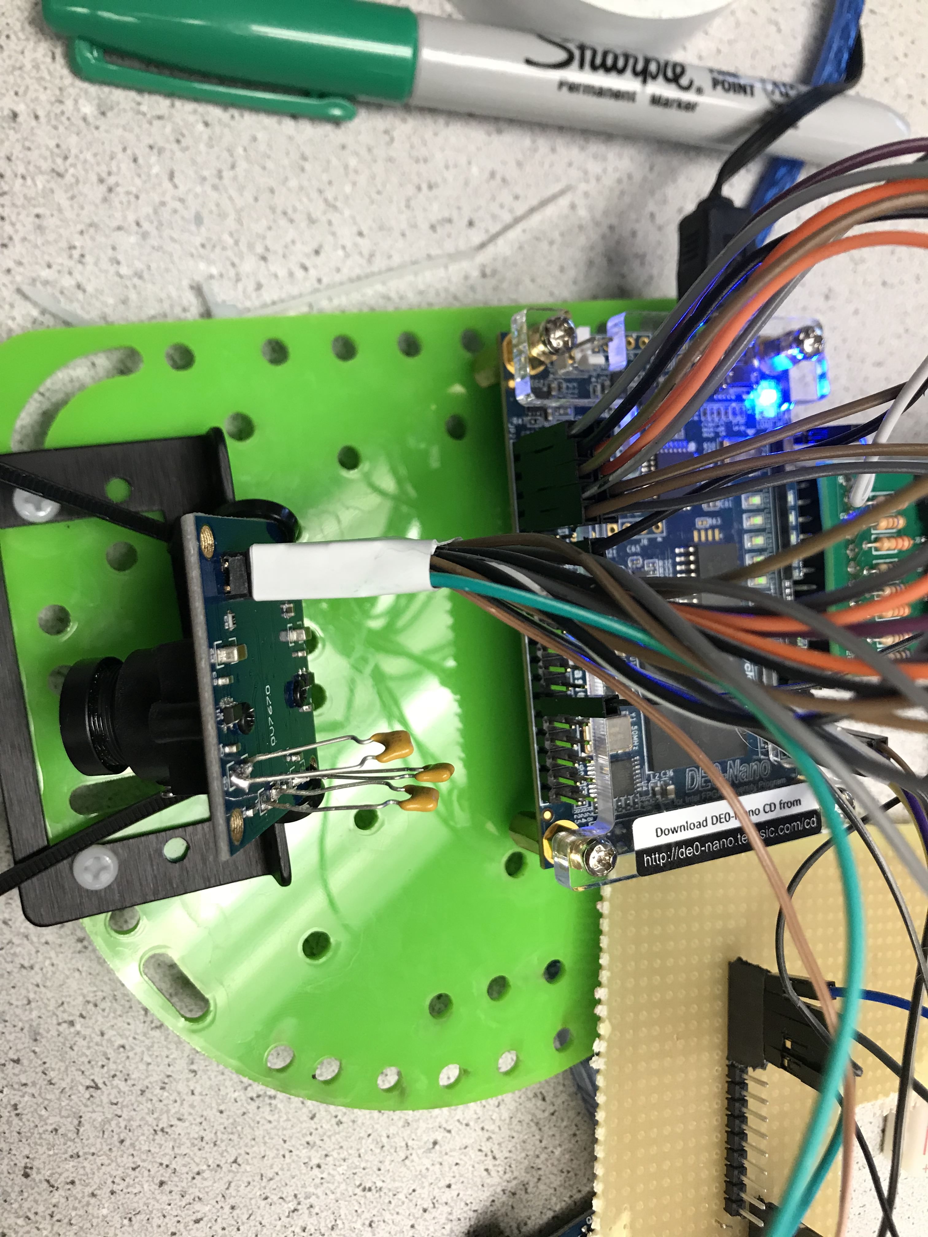
The camera contains 20 pins total. We have 8 pins for parallel data which sends one of the two bytes for pixel during each clcok cycle. These eight pins are connected to input GPIO pins on the FPGA. In addition, we also have HREF and VSYNC pins which are also connected as input to the FPGA. The camera also has PCLK and XCLK pins. The XCLK is for external clock. We use an output pin from the FPGA and put it to the camera. The PCLK is camera clock; we route that back to the FPGA for analysis.
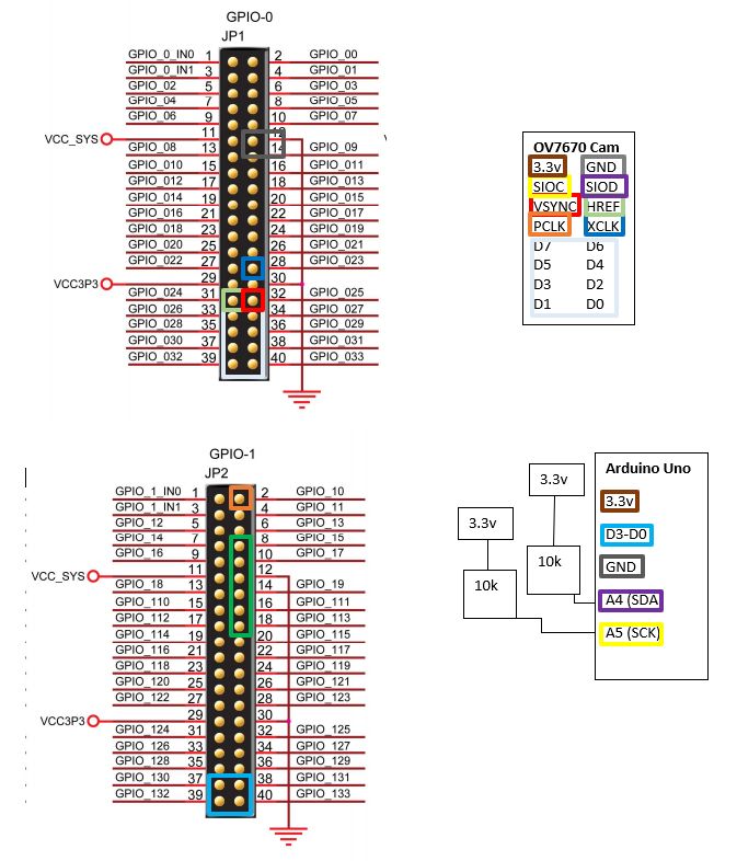
In the figure above, the colored rectangles mean that the pins are wired together.
In the FPGA, we must set the camera communication pins, HREF, VSYNC, and PCLK to input for the FPGA. We set the the communication pins with the Arduino as output. In quartus, this is done as follows:
//////////// GPIO_0, GPIO_0 connect to GPIO Default //////////
output 		    [33:0]		GPIO_0_D;
//////////// GPIO_0, GPIO_1 connect to GPIO Default //////////
input 		    [33:20]		GPIO_1_D;
We also use four parallel wires for communication from FPGA to the Arduino. We have two bits for treasure shape and two bits for color.
Polling from camera
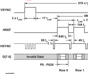
The above timing diagram shows us how images from the camera are sent. When we have a new frame incoming, the VSYNC goes high. After some time, the HREF will go high, signalling the start of the first byte of data. The camera can send data in RGB565 which is 5 bits of red, 6 bits of green, and 5 bits of blue color. This is divided into two transmissions due to the camera’s one byte communication line. When the HREF goes high, the camera is transmitting the data for the first row of data. A low HREF means that we finished transmitting data for one row. At this point, the VSYNC can go high to signal the end of the image or the HREF can go high again when the camera is sending data for the next row of pixels.
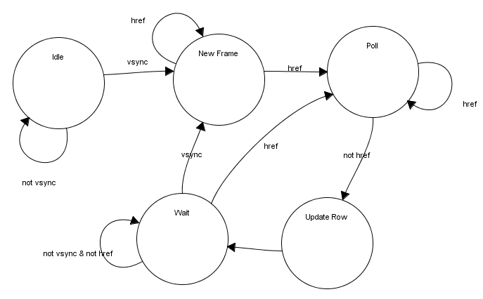
Based on the timing diagram, we created this state machine to model the behavior of the camera transmissions.
| states | Function |
|---|---|
| IDLE | Start of device. We wait here for camera to start |
| NEW FRAME | Start of new frame where we reset the X and Y address |
| POLL | Enable to downsampler and poll from camera |
| UPDATE ROW | New row of pixels. Update Y address and reset X address |
| WAIT | Wait for start of next frame or row |
always @(*) begin
    case (control_state)
        STATE_IDLE: begin
            W_EN                <= 1'b0;
            down_sample_reset   <= 1'b1;
        end
        STATE_NEW_FRAME: begin
            down_sample_reset   <= 1'b0;
            W_EN                <= downsampler_rdy ? 1'b1 : 1'b0;
        end
        STATE_POLL: begin
            down_sample_reset   <= 1'b0;
			W_EN                <= downsampler_rdy ? 1'b1 : 1'b0;

        end
        STATE_UPDATE_ROW: begin
            down_sample_reset   <= 1'b1;
            W_EN                <= 1'b0;
        end
        STATE_WAIT: begin
            down_sample_reset   <= 1'b1;
            W_EN                <= 1'b0;
        end
        default: begin
            W_EN                <= 1'b0;
            down_sample_reset   <= 1'b1;
        end
    endcase
end

always @(posedge pclk) begin
	case (control_state)
        STATE_IDLE: begin
        end
        STATE_NEW_FRAME: begin
            X_ADDR          <= 15'b0;
            Y_ADDR          <= 15'b0;

        end
        STATE_POLL: begin
			//increments xaddr after downsampler
            //finishes and writes to mem
			X_ADDR <= downsampler_rdy ? X_ADDR + 1 : X_ADDR;

        end

        STATE_UPDATE_ROW: begin
			Y_ADDR			<= Y_ADDR + 1;
            X_ADDR          <= 15'b0;
        end
        STATE_WAIT: begin

        end
        default: begin

        end
    endcase
end
We must save the data from the camera into a memory location so that it can be read by the VGA and the image processor later for analysis. This is done with two variables, X_ADDR and Y_ADDR.
Downsampler
<p ALIGN=LEFT> The camera’s eight parallel data pins output color per pixel at a clocked rate. For RGB, it uses the configuration for RGB565 or RGB555. Both configurations are two bytes in length total which means that each pixel captured by the camera are two bytes. We must downsample the two byte data from the camera to 1 byte data because of memory constraints on the M9k memory blocks on the FPGA. We can only store one byte of data per memory address. Thus we must convert to RGB332 or RGB323. We used RGB332 for debugging and displaying the camera data on the VGA screen since the VGA only takes in RGB332 values. For treasure detection, we changed to RGB323 to get more bits out of the blue pixel since we are only detecting blue and red treasures. The goal of the downsampler is to take the two byte pixel from the camera and converted it to a one byte pixel. This one byte pixel will be saved into the M9k memory block at the correct memory address which is relative to the pixel location on the screen. <>
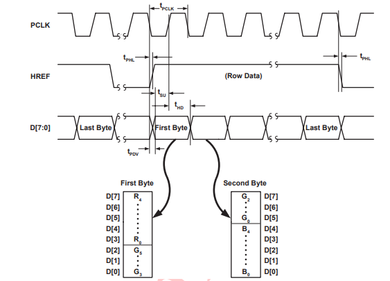
| states | Function |
|---|---|
| IDLE | wait for start of reading |
| READ | start reading from camera |
READ: begin
    fsm 		= (VSYNC || RES) ? IDLE : READ;

    if(HREF) begin
        count_bit 		= ~count_bit;
        if(count_bit) begin
            reg_valid		<= 1'b0;
            OUT[7:2]		<= {D[7:5], D[2:0]};
        end
        else begin
            reg_valid 		<= 1'b1;
            OUT[1:0]		<= D[4:3];
        end
    end
    else begin
        count_bit			<= 1'b0;
        reg_valid 			<= 1'b0;
        OUT					<= 8'd7;
    end
end
Color Bar
To display the color bar, we must set the appropriate registers in the Camera. The main registers involved are COM 7 and COM 17 for color bar enable and color bar DSP enable. With the downsampler above, we are able to decode the bytes coming from the camera and display the color bar onto the VGA screen. The downsampler takes in input from the camera.
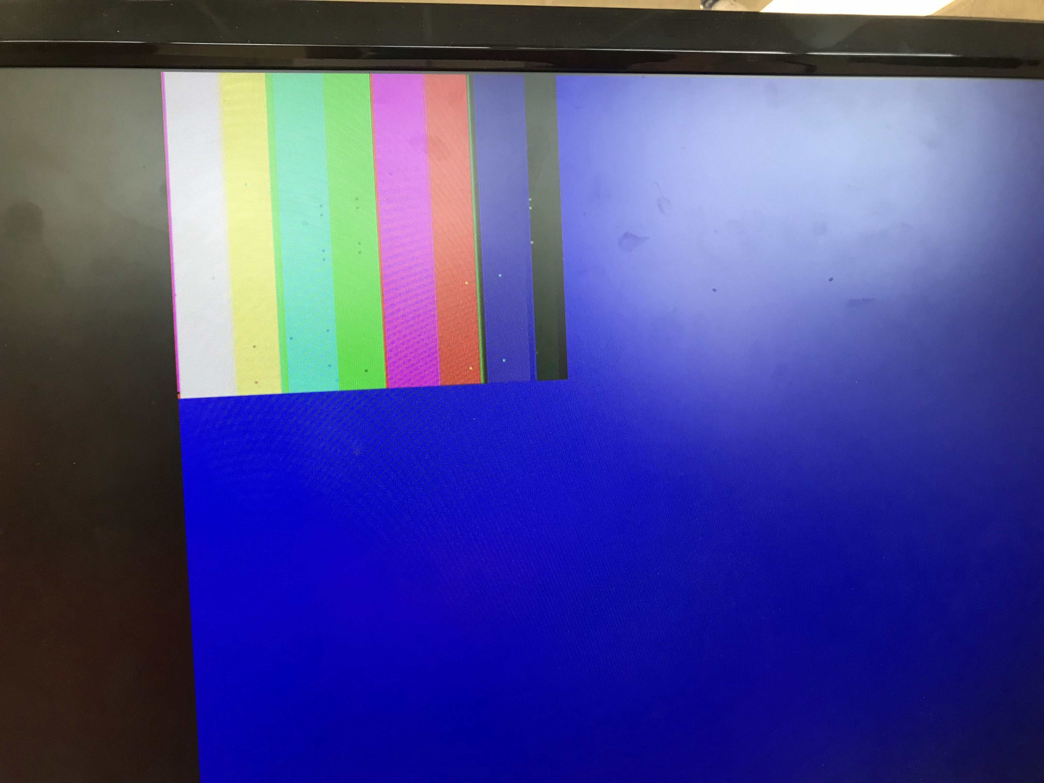
The colors in the bar are different from the example in the lab but when we use the camera to capture, we found that the colors were passable and would not pose an issue.
Display Camera Capture
To display the images captured by the camera, we must set the registers from the Arduino. We can disable the DSP for color bar and the color bar test itself. The FPGA code is exactly the same.
Color Detection
For color detection, we use a module call the Image Processor. The image processor samples at the same rate as the VGA board at 25 MHz. We set a boundary within the resolution of each image and then count the amount of blue and red in each pixel.
always @(posedge CLK) begin

	if (VGA_PIXEL_Y <=20) begin
		blueCount  = 0;
		redCount   = 0;
		greenCount = 0;
		done_color = 1'b0;
	end
	else if (VGA_PIXEL_X > `X_LOW_THRESH && VGA_PIXEL_X <
    `X_HIGH_THRESH && VGA_PIXEL_Y > `Y_LOW_THRESH && VGA_PIXEL_Y <
    `Y_HIGH_THRESH) begin
		blueCount = blueCount + blue;
		redCount  = redCount  + red;
		greenCount = greenCount + green;
	end
	else if(VGA_PIXEL_Y >= `Y_HIGH_THRESH && !done_color) begin
		if (greenCount > 15'd5000 && blueCount > 15'd20000 &&
        redCount > 15'd20000) begin
			color = NONE;
		end
		else if (blueCount > redCount && (blueCount - redCount) > 30
         && blueCount > 15'd200) begin
			color = BLUE;
		end
		else if (redCount > blueCount && (redCount - blueCount) > 30
        && redCount > 15'd200) begin
			color = RED;
		end
		else begin
			color = NONE;
		end
		blueCount = 0;
		redCount  = 0;
		greenCount = 0;
		done_color = 1'b1;
	end
end
This implementation use a lot of variables. We needed a counter for the three colors. We used the counter to count the values of the blue and red pixels if they are within a set of boundary. The boundary was used as a filter so that we can get the values that are near the center of the camera screen since that was where the shapes are most likely going to be. We judge as soon as the VGA X and Y axis exit the high threshold which means that we are approaching the end of our image. As shown above, we compare the counters of red and blue pixels and see if one is greater than the other by some threshold. We need the green counter because if the green counter is high while red and blue are also high, it likely means that we are viewing a white wall since there are no green color shapes. The judging only occurs once which was done by a flipping bit. We also reset the counters for the next frame.
Arduino
Disabling Arduino’s Internal Pullup resistor
In the prelab, we determined what registers we needed to set and what values we needed to set them to in order to properly set up the camera to do what we need it to. Before starting anything, we disabled the internal pullup resistors in the Arduino’s I2C interface so as not to damage the camera by sending 5V to it. We then downloaded the provided Lab 4 Arduino template in order to use the functions provided in it to write to and read from registers in the camera. With these functions, we
This is done by going to the Arduino library on our hard drive. This is done by going to twi.c at C:\Program Files (x86)\Arduino\hardware\arduino\avr\libraries\Wire\src\utility and commenting out
    //activate internal pullups for twi
    digitalWrite(SDA,1);
    digitalWrite(SCL,1);
This will allow the I2C interface to communicate with the camera without sending 5v to the camera.
Writing Registers
We use the I2C communication protocol to talk to the camera. This is setup using Arduino’s Wire library which supports I2C interfaces. We set up the Arduino as the master and the camera as slave. The camera has a set slave address of 0x21 after we ignore the least significant bit because that is used to distinguish between read and writes. The Wire library already set this up for us. All we have to do is pass the upper seven bits of the slave address of the camera to the I2C interface. We write to the camera by calling:
    Wire.beginTransmission(0x21); // 7-bit Slave address
    Wire.write(value_to_write);
    Wire.endTransmission();
The library makes it super simple to communicate with the camera using I2C.
To have the camera capture the images we want, we must set some registers on the camera that deal with resolution, and camera clock. The following shows how we wrote to the registers:
void setup() {
    Wire.begin();
    Serial.begin(9600);
    delay(100);
    Serial.println(OV7670_write_register(0x12,0x80));
    //color bar test
    //  Serial.println(OV7670_write_register(0x12,0x0E));
    //  Serial.println(OV7670_write_register(0x42,0x08));

    Serial.println(OV7670_write_register(0x12,0x0c));
    Serial.println(OV7670_write_register(0x0c,0x08));
    Serial.println(OV7670_write_register(0x14,0x11));
    Serial.println(OV7670_write_register(0x40,0xD0));
    Serial.println(OV7670_write_register(0x11,0xC0));
    Serial.println(OV7670_write_register(0x1E,0x30));
    set_color_matrix();
}
| Registers | Name | Function |
|---|---|---|
| 0x12 | COM7 | Reset regs; enable/disable color bar test; sets QCIF 176x144 resolution |
| 0x0c | COM3 | Enable scaling |
| 0x14 | COM9 | Auto gain ceiling 2x; Freeze AGC/AEC |
| 0x40 | COM15 | Max output range [00] to [FF]; Use RGB 565 |
| 0x42 | COM17 | DSP color bar enable |
| 0x11 | CLKRC | Use 24 MHz clk from FPGA; pclk can be as high as xclk |
| 0x1E | MVFP | flip and mirror image |
We set the camera to QCIF resolution which is 176 x 144 screen size. This is the smallest resolution the camera supports. We use this resolution because we lack memory to store any larger sizes on the FPGA. For the first part of the lab, we tested the camera and our FPGA polling code by using the camera color bar to make sure we can display the correct colors on the VGA screen. This means we have to set COM7 to display the color bar and enable DSP color bar in COM 17. The other important setting is the camera clock. This camera clock determines the rate a which each pixel is sent to the FPGA. We drive the camera with the 24 MHz FPGA clock. This gives the camera the ability to go up to 24 MHz for pixel transmissions.
Communicating with FPGA
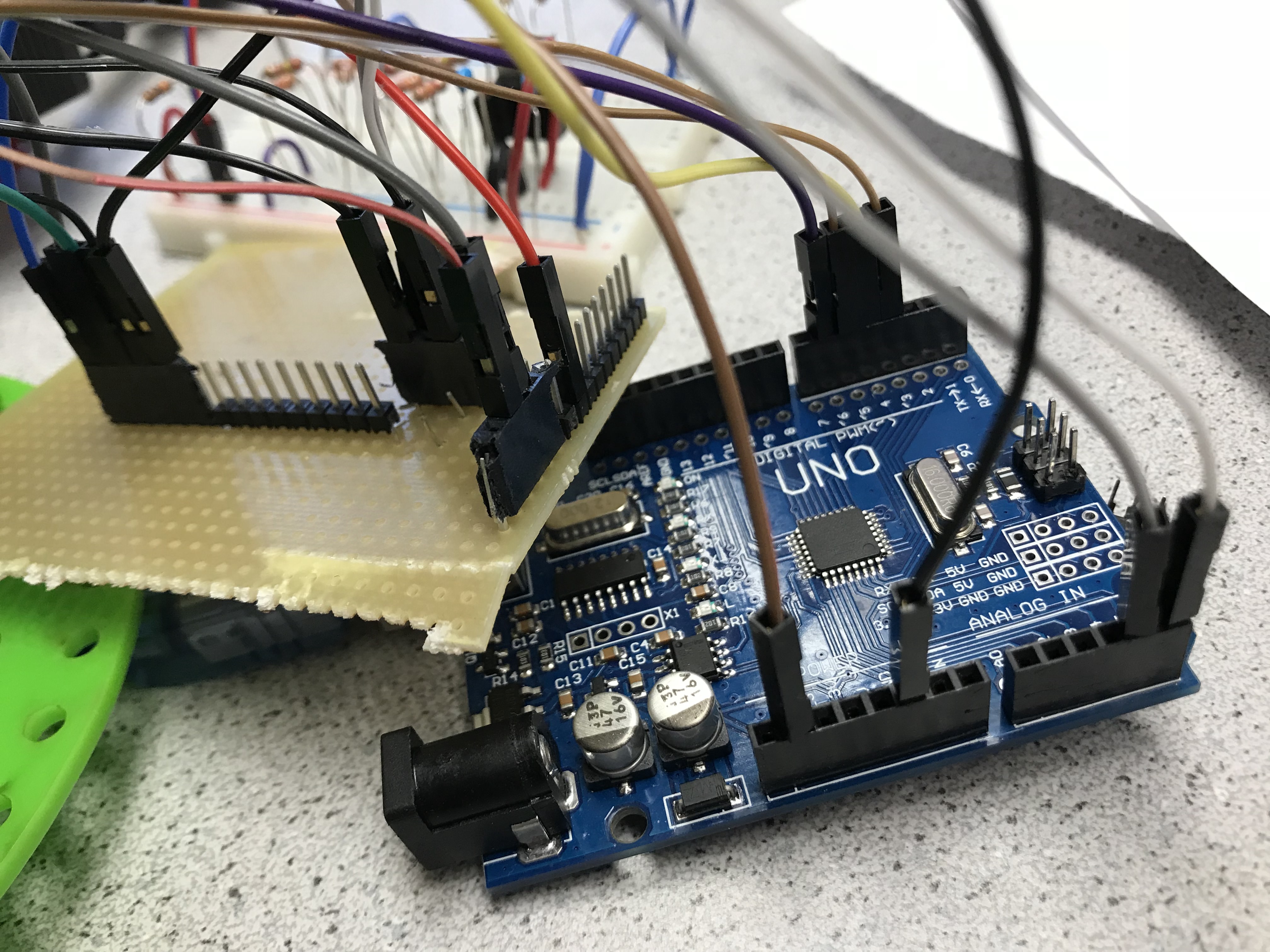
Communication with the FPGA is done by wiring the GPIO pins on the FPGA to the arduino in parallel. We use combinational logic in this case since we set the FPGA to output the results of the image processing immediately while having the Arduino constantly decode the message for the four pins. Even though the voltage of the Arduino pins are 5V while FPGA pins are 3.3V, we can connect the pins together without a voltage divider because the Arduino pins are set as input and are capable of reading the 3.3V from the FPGA as high.
Initially, we define the input communication pins on the Arduino and the decoding treasure numbers.
#define T1 3   //GPIO 33 treasure[0]
#define T2 4   //GPIO 32 treasure[1]
#define C1  5  //GPIO 31 color ; blue or red
#define C2  6  //GPIO 30 color ; blue or red
#define RED 2
#define BLUE 1
#define NONE 0
#define SQUARE 2
#define TRIANGLE 1
#define DIAMOND 3

uint8_t decoder(){
  uint8_t treasure1 = digitalRead(T1); //read from pins
  uint8_t treasure2 = digitalRead(T2);
  uint16_t color1   = digitalRead(C1);
  uint16_t color2   = digitalRead(C2);
  Serial.print("T1: ");Serial.print(treasure1);
  Serial.print(" T2: ");Serial.print(treasure2);
  Serial.print(" C1: ");Serial.print(color1);
  Serial.print(" C2: ");Serial.print(color2);
  uint8_t treasure  = (treasure2 << 1)|treasure1;
  //combine treasure bits
  uint8_t color   =   (color2<<1)|(color1);
  Serial.println("");
  Serial.print("---COLOR: ");
  if(color==BLUE) Serial.print("BLUE");
  else if(color==RED)    Serial.print("RED");
  else             Serial.print("NONE");
  Serial.print( " Treasure: ");
  if( treasure == SQUARE)
      Serial.print("SQUARE");
  else if( treasure == TRIANGLE)
      Serial.print("TRIANGLE");
  else if( treasure == DIAMOND)
      Serial.print("DIAMOND");
  else
      Serial.print("NONE");
  Serial.println("");
}
This code is the decoder for communication from the FPGA. The code is very simple because of the extra hardware used. With this method, we used up to four pins from the Arudino. We could have used a serial communication protocol using two pins to send the four bits of messages but we have extra pins from the Arduino left over so simplicity at the cost of hardware was prioritized.
Conclusion
This lab is one of the harder labs this semester. Getting the camera to display an image correctly was a challenge due to the complexities in timing the camera pixel transmission correctly. While getting the image itself wasn’t too difficult to display, getting the right colors for the image was difficult. We often had inverted colors or colors that were too dark or faded displaying on the screen. Both hardware and software contributed to the difficulty. We had to set the software to poll the bytes from the camera correctly but also had to ensure sure we wired the camera to the FPGA in a way that wouldn’t introduce noise, especially with a 24 MHz clock driving the transmission. Looking forward, we will be integrating the FPGA camera system into our robot. This will likely result in more states and updates to our radio messages to support communicating treasure shapes and colors. We also will need to update the basestation so that it can receive messages from the radio.